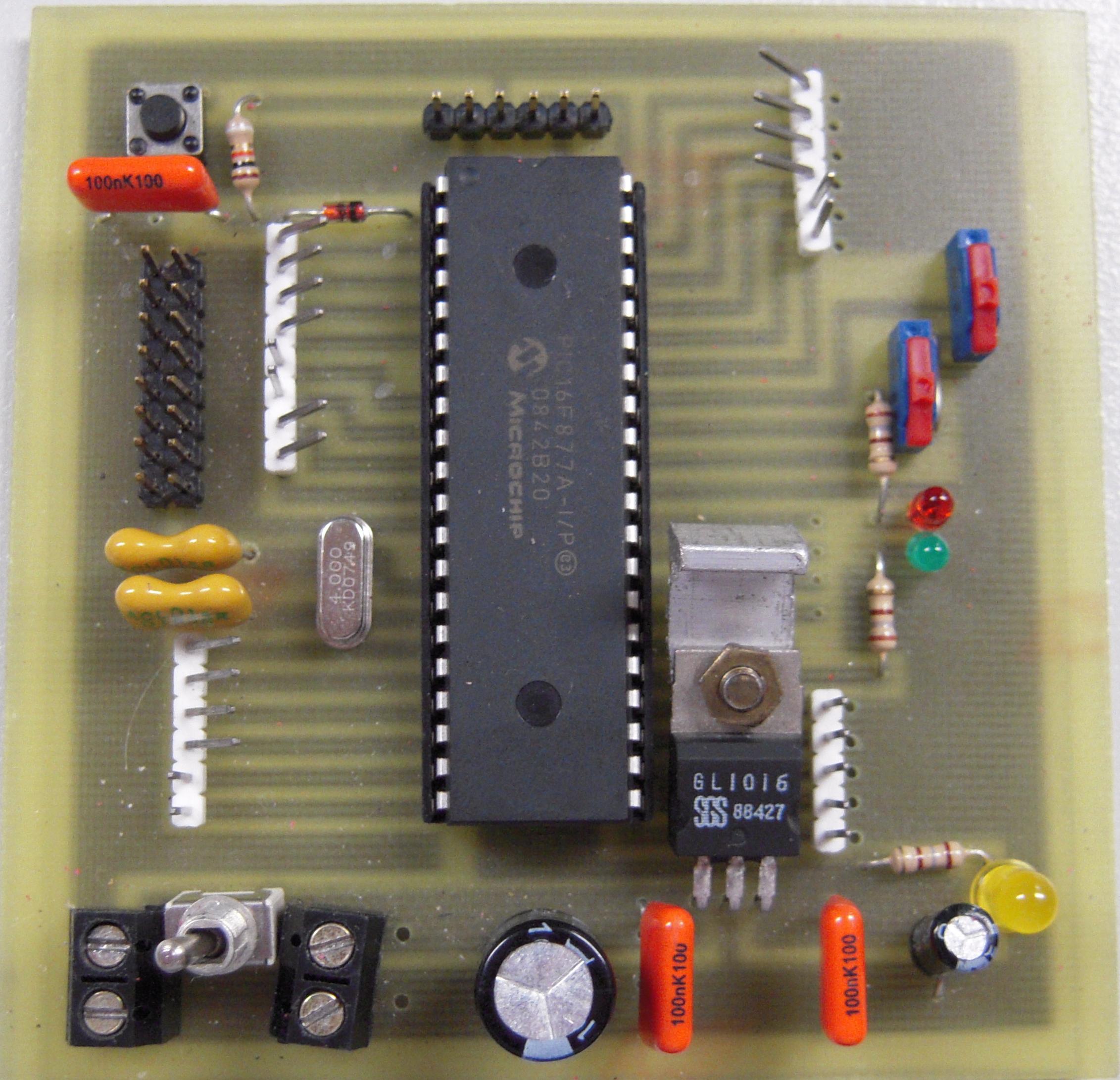
The microcontroller we used is a PIC16F877A from Microchip.
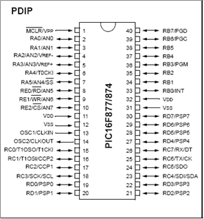
We used the 40-pin version; because we needed the 8 analogue inputs (the 28-pin version has only 5 analogue inputs).
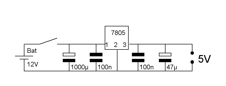
The power supply
The microcontroller needs energy to work. The microcontroller needs a DC power supply between 2 and 5.5V. You can use an external power supply or batteries. It is advised to use a stabilized 5V power supply especially if other digital IC’s will be connected to the microcontroller because 5V is usually the logic 1 for many IC’s. The PIC16F87XA needs the 5V at pin 11 and 32 (Vdd) and pins 12 en 31 (Vss) connected to the ground (0V-GND).
This circuit makes out of a DC voltage between 18V and 7V a stabilized 5V and uses the voltage regulator LM7805.
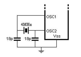
The clock signal
The microcontroller runs on a certain frequency, the clock frequency. The pins OSC 1 (pin 13) and OSC2 (pin 14) deliver the clock signal to the microcontroller. Therefore an oscillator (crystal) needs to be connected using the following circuit.
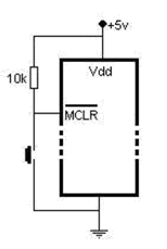
Reset
In case the microcontroller doesn’t react anymore or is blocked or stopped, we integrated a reset button in the circuit.
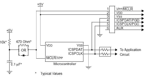
In-circuit serial programming (ICSP)
In-circuit serial programming (ICSP) gave us a convenient way of programming the PIC microcontroller, without removing the chip from the PCB.
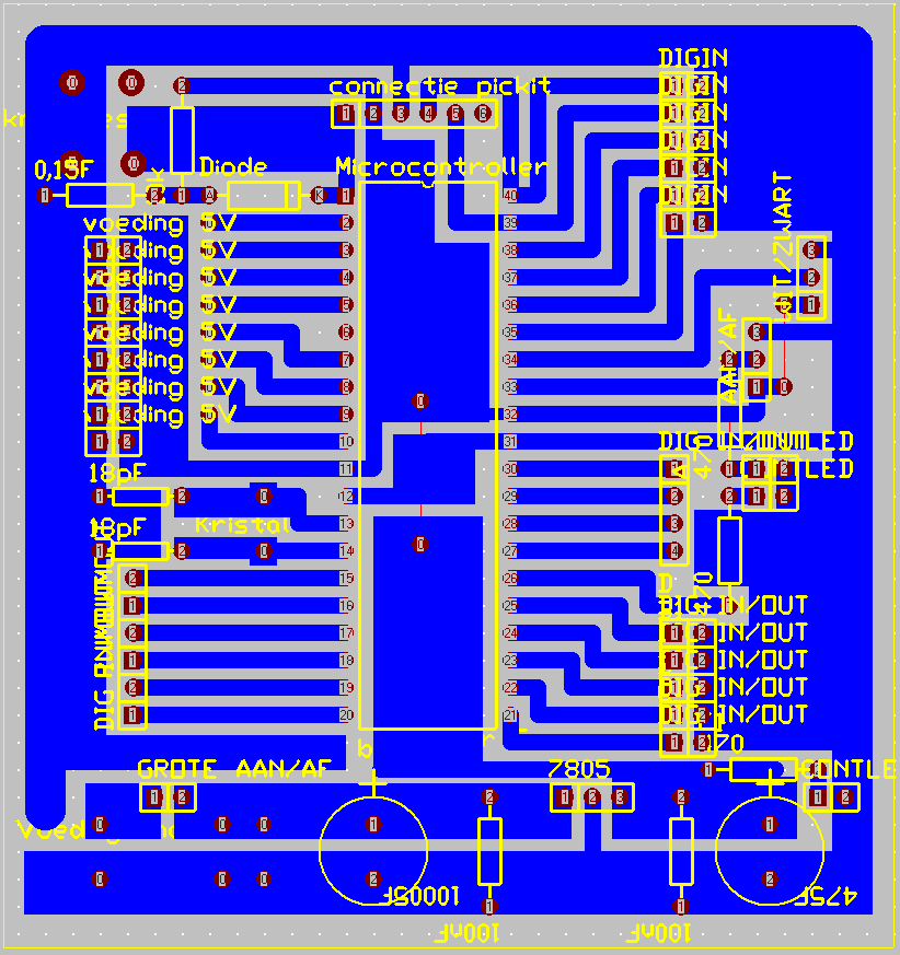
Traxmaker
All these electric circuits were put together on one PCB. The final Traxmaker design is shown below.
Copyright © 2009 • Ward De Paepe • All Rights Reserved |