Mechanics model:
Guidelines
1. Limited dimensions
We wanted to keep the dimensions of the robot reasonable, essentially for aesthetic
purposes.
2. Mobility
The whole assembly should be easily transportable.
3. Sturdiness
The device must resist to a normal use.
4. Good hiding of the electronics
Parts such as wires, PCBs, etc. should be concealed and invisible to the user once the robot
is assembled.
5. Ease of assembly
The assembly had to be kept in mind during the design of all the parts.
6. Reasonable budget
We wished to avoid too much expensive parts.

In order to prepare the design of our robot, the first step was to establish a list of the
specifications that we wished:
Material choices
These requirements being settled, a first design was conceived. Before presenting it, let’s
review the different material choices that were made:
External case
The material chosen for the case is wood. Firstly because of its opaque nature, allowing us
to hide the electronic components inside the case. Since laser cutting was planned to obtain
the parts, we narrowed the research to two possible materials: multiplex or MDF.
Positioning system
As explained in the homepage of this website, the principle of our robot is to write the time
on a surface and erase it continuously. To do so, it has to be able to move the writing
device in two directions. This implied a review of the different 2D-positioning systems that
could be applicable. In other words, we had to find a way to transform the rotation
movement of our motors into a linear motion. Three systems were retained:
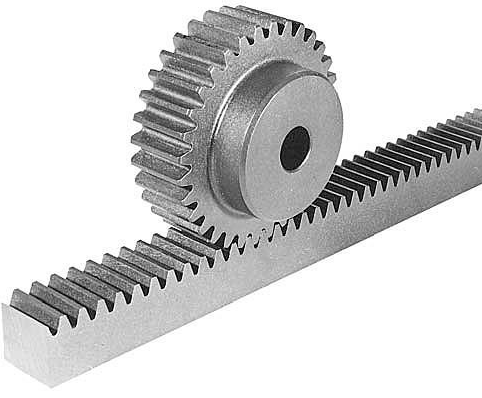
The first system considered is composed
of a conventional spur gear and a rack.
It has the advantage of being quite
compact and its parts are easy to find.
It could even be manufactured by
ourselves (through 3D printing).
1. The gear and rack drive
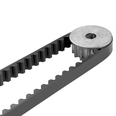
2. Belt drive
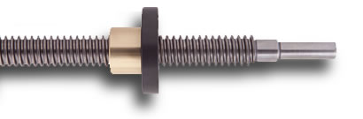
3. Leadscrews
This system has good accuracy but was
quickly abandoned because of its size
and more importantly the cost of its
parts.
We also thought of using pulleys and
belts to achieve the positioning.
Although the slip problem is less
important than for the gear and rack
system, they need more room because
a tensioning system must be added to
ensure its good operation.
Finally, for the first design, we chose the gear and rack system. Indeed, we appreciated
the fact that it was easy to obtain and to place on the structure.
Writing head
After the problem of positioning had been dealt with, we had to find a way to achieve the
up-and-down movement of the writing head on the surface (determining when the tip is
writing or not). Two systems were considered:
In the end, our choice was to use the solenoid. Its control is simple and its dimensions are
restricted.
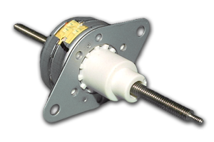
1. DC motor/servo/stepper with screw
System consisting in a small motor
connected to a screw shaft. The
writing tip should then be connected to
a threaded part to achieve linear
motion.
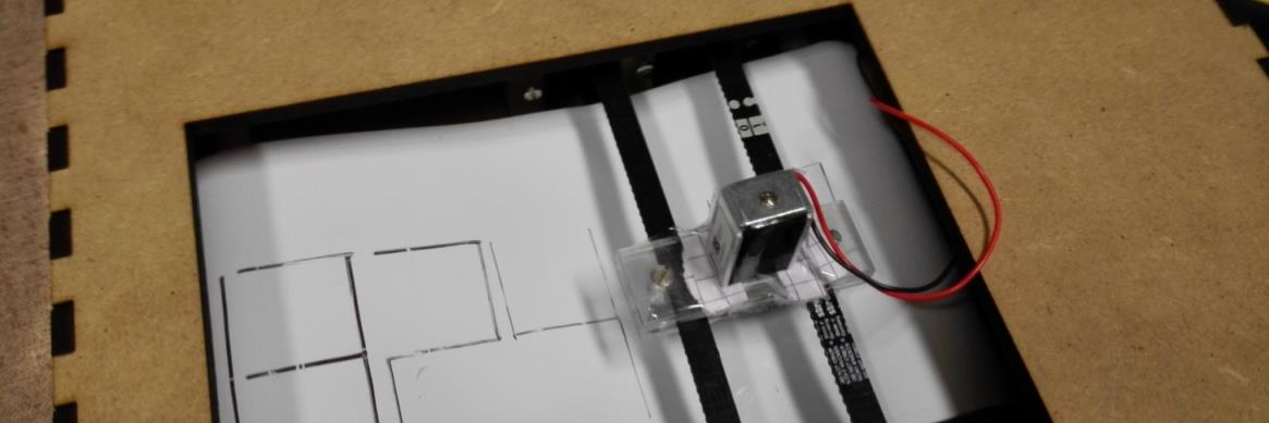
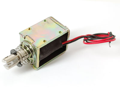
The other possibility was to use a
solenoid. This device generates a
magnetic field that is able to push or
pull the metallic shaft. It is more
compact than the previous system.
2. Solenoid
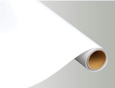
At first, we considered using a piece of a conventional
whiteboard as a support for writing the time.
However, this choice was abandoned to the profit of
“whiteboard film”, a flexible writing surface
presenting the same characteristics as a whiteboard.
Writing surface

First design
Description
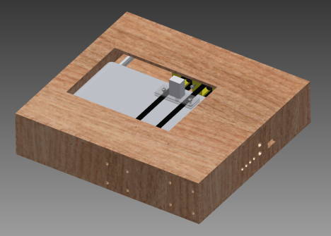
Once the choice of the different components had been made, we could begin the
development of a model. This was done using Autodesk Inventor:
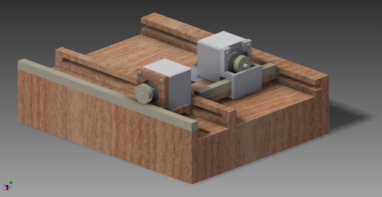
As seen on the picture, the positioning system lies on top of the global assembly. Both the
x-axis and y-axis movements are provided by motors and gear-and-rack transmission
systems. The two motors stand on a mobile wooden part that is guided by “rails” on two
locations. One of the motors is attached by screws directly to the wooden part and the other
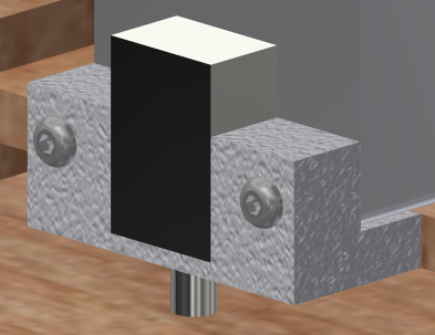
is unified to a sliding plastic piece (3D-printed). To hold the solenoid in place, a second 3D-
printed support is considered. To erase the time, a standard whiteboard eraser would be
placed on the stepper support.
Issues
Although this design helped us to get information on the different components available to
realise the robot, it posed four important problems:
Second design

1. Friction
As most of the wood used for laser-cutting have a rough surface, it is
probable that the mobile wooden part would have difficulties sliding on its
rails. A potential solution would be to use another material such as
plexiglas.
2. Only one side of the slider is driven
This could cause the wooden slider to rotate and then to block.
3. Two motors on the slider
This might cause overload on the motors due to the important mass.
4. Assembly problems
For the first design, a screw assembly was considered. This could have
caused issues at some points where many parts must be assembled (e.g.
the bottom part, the cover and the rail).
All in all, these issues (mainly the friction issue) caused us to drop this design and restart
from scratch.
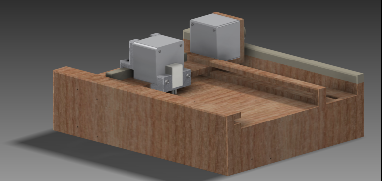
The second concept was designed to avoid the previous problems:
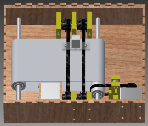
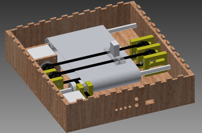
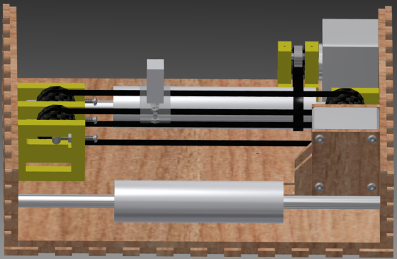
It contains numerous improvements over the first concept:
1. More compact
The first thing to notice is that it has been made more compact since now
all the components are in the same space.
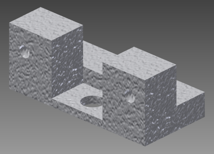
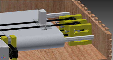
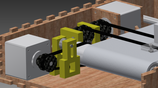
2. Positioning system
Movement along the vertical axis is now ensured by two belts. On these
two belts, a support formed of 3 plexiglas layers is design to hold the
solenoid in place. To adjust the tension of the belts, we imagined a new
system. It is composed of three identical 3D-printed pieces, three bolts and
an axle. The pulleys are mounted on the shaft and it is then possible to set
up their position by screwing the bolts, giving result to more or less tension
on the belts. For the horizontal movement, two shafts support PVC tubes
(using bearings). Around these PVC tubes, the whiteboard film is rolled. To
achieve the rotation, the stepper motor is connected to the right PVC tube
thanks to a belt. The tensioning system is similar to the one described
above. Note that this time, to erase what is written on the whiteboard
film, an eraser is placed under it.
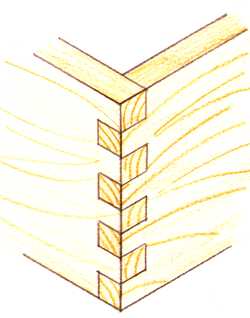
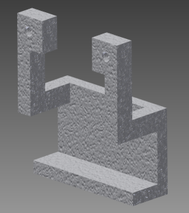
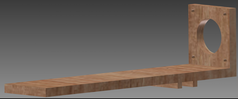
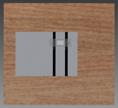
3. External case and supports
The material for the case was kept the same as
before (MDF). However, to assemble the
different panels, a “finger joint” assembly was
chosen. This allowed us to avoid using screws
and to give a nice look to the exterior of the
robot. Of course, to make the case sufficiently
strong, the use of wood glue was considered. On
top of this modification, three panels were
added to house the different mechanical
components and ensure global stiffness of the
robot. The supports for the vertical axis stepper
were designed to be laser-cut in the same
material as the case.