

Assembly:
Test of the code
To facilitate debugging, we first tested the .ino codes on breadboards. Indeed, test the
code for the first time on the fully assembled robot can cause bad surprises. Each part of
the code has been separately tested on an assembly which had the good electronic
components. One of the tests can be found here (test of the potentiometer and the leds on
the breadboard) while an other one is shown just below.
Test of the two steppers on the breadboard
PCBs assembly

Manufacturing of the mechanic parts
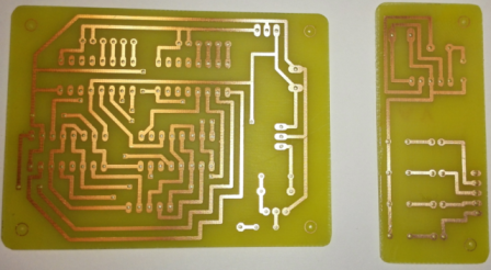
As the Eagle boards were made (see here), both PCBs have been produced:
We started with the small PCB because there are fewer
components to place and therefore the risk of errors was
lower. it was the first time that we soldered, the result was
convincing.
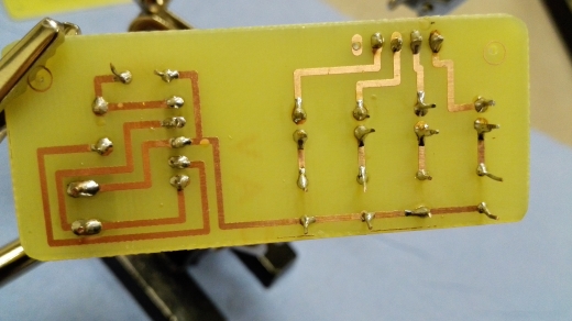
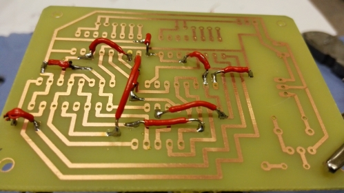
So we weld the second PCB. The first step was to place the jumps. It was not easy because
they were small. But despite the slight melting of insulation, the welds are good and it is the
most important.
The two techniques chosen to manufacture the parts of our robot were the laser cutter and
the 3D printing. We used the laser cutter for the external case (MDF) and for the support of
the solenoid (plexiglas) while we used the 3D printing for the seven pieces which adjust the
tension of the belts. See Technical Details - Mechanics model for more details.
To use this type of equipment, we went to the Brussels Fablab. One video of each
technique and a picture of one of our 3D printed pieces can be found just below.
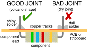
So we had to solder the electronics
components on the boards at the right places.
We also had to pay attention to make correct
soldering, as shown on Figure, in order to
avoid connection or fragility problems.
Once the jumps were placed, we tested, using a multimeter, if there were short-circuits.
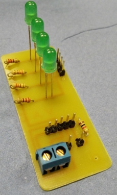
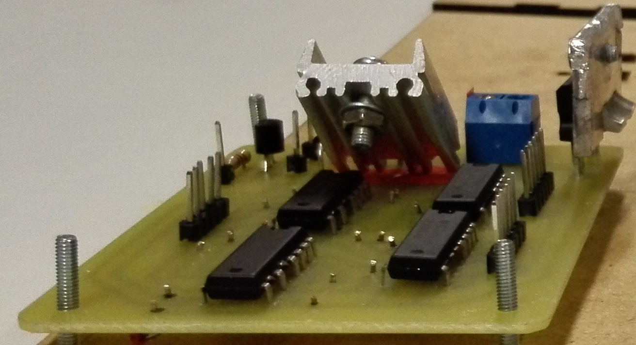
Since there was none, we were able to place the rest of the components with two extra
radiators to cool the power chips.

3D Printing @ Brussels Fablab
Laser Cutter @ Brussels Fablab
Test of the partly assembled robot
Assembly of the robot

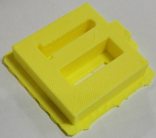
One of our 3D printed pieces
 |
 |
 |
 |
 |
 |
 |
 |
 |
 |
 |
 |
 |
 |
 |
 |
 |
 |

Once all the pieces were available, we proceed to the assembly of our robot following this
sequence:
Step 1
Mounting the bottom of the box
with two side portions and
assembly of one motor and two
3D pieces.
Step 2
Mounting the PCB on the bottom
of the box.
Step 3
Assembly of three 3D pieces on a
side portion.
Step 4
Assembly of the background and
the PVC tubes.
Step 5
Assembly of the third side
portion with the box.
Step 6
Assembly of the second motor
and the last two 3D pieces.
Step 7
Placing the belts and the support
for the solenoid.
Step 8
Assembly of the small PCB on the
last side portion and closing the
box
This sequence is illustrated by the Mounting sequence gallery:
Mounting sequence
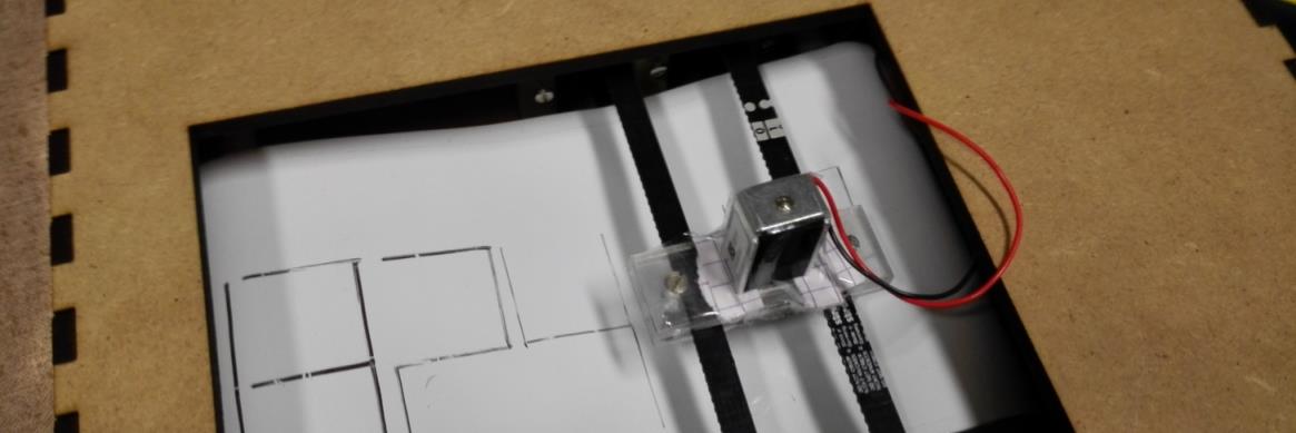
We also performed various tests during installation to check that everything was working as
expected. One of these tests is available in the video just below: we were testing the
functioning of the motors with the belts.
Click to open