
Practical realisation
To see if the different parts of the circuits worked, they were tested on a breadboard.
Generator
The generator worked quite good, the voltage supply was fixed at 16 V (not at 18V as mentionned in philohome site because it would be nefast for the timer which maximum voltage supply should be 16 V, see Datasheet). The results are shown in the following video and pictures where :
-A square wave is observed at the output of the timer (before the band pass filter)
-A sinusoïdal wave with the required frequency is measured with an oscilloscope at the output of the circuit.
Square
Sinusoid
Sensor
The practical realisation of the sensor failed.
The signal is sensed by the coils as you can see on the video below so this was ok.
PUT HERE A VIDEO I WILL MAKE LATER
But the diodes of the rectifier amplificator did not fulfil their function and the signal at the output of the circuit with diodes was not like expected in theory. Thus the circuit was made again 3 times with another breadboard and with other components but still the result was very bad.
What we decided to do is to verify the circuit in Matlab and we found that it should normally work in theory. Perhaps the components chosen were not good, but we used the one Philohome used thinking it would work. What could have been done to improve the sensor circuit would have been to compute how much current was flowing in the resistors and perhaps adapt those resistances in consequence. In fact the voltage sensed by the coils is very low (5 mV peak to peak), when for philohome it seemed to be higher. We tried thus to increase the gain by tuning the resistances but even it did not work. What we though was perhaps that in general the resistances were to high so perhaps we should have designed the resistances ourself, and using lower values.
After losing a lot of time to find solutions and because there was no enough time left before the deadline, it was decided to change of strategy by making a simple line follower robot so we get a result in practice and we could test our code.
The schematic of the designed sensor chain acquisition is here below :
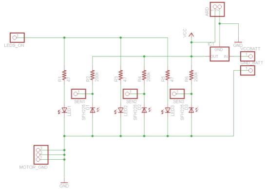
The pcb of this part is shown HERE
The principle of this sensor is very simple. An infrared wave is sent to black or a white line, and the reflexion is sensed by IR photodiodes.
-If black line : less infrared wave is reflected since it is absorbed by the black color
-If white line : more infrared wave is reflected since it is reflected by the white color
The resistors R1, R3 and R5 are to limit the current flowing in the LEDS whose resistances are very low.
The pins SEN1, SEN2, SEN3 are sensing the voltage on the photodiodes which is lower when infrared is sensed by the photodiodes since current will flow and the upper resistors will take a part of the voltage supply VCC (V=R.I).
With the realisation on the breadboard we had some problems in practice because the up-resistors of the photodiodes were to low and did not take enough voltage from VCC. We increased them thus to get 200kOhms resistors (10kOhms before).
Also one had to look at which voltage the LED’s were best used and to adapt the values of R1, R3 and R5 with respect to that (we had to lower the resistors advised on a site to get more or less 1.2 V on the LED’s, value given in their Datasheet).
Finally, the sensors were tested with a black and white paper to verify they worked, and we got good results.
The code used to control the motors knowing the position of the robot with respect to the black line is explained and shown HERE.
Finally those sensors were fixed on the robot and the code was tranfered in series to the arduino.
The robot was tested and first we had some issues because the robot was not able to turn when the curve was too high.
-One had to adapt the velocity and the rotation parameters in the code by trials and errors to get much better results.
-Also the robot was better balanced by inserting a load in it.
-The delay in the Arduino code after each loop was also adapted to get a more fluent motion.
Finally, the robot fulfilled its requirements very well as you can see in the following video.