
PCB design
The PCB design is devided in two part, the schematic and the board. To get a good board it is important to make the schematic without any mistake.
First we needed a pcb for a wire following robot. Later due to some issues, a black and white line follower was chosen to replace the previous unsuccesfull plan.
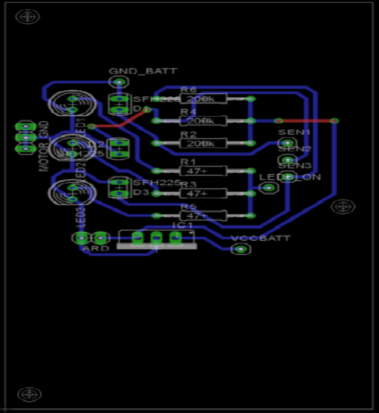
Once the schematic is perfectly done, the board must be designed.
It is important to give a certain angle to the curves of the wires. The width of the wires are all of 0.024 m because it is the maximum value where wires can pass between the pins of the OP-amp. It is also important that between one line and another there is a space as big as the dimension of a wire so the technician can make the PCB easier.
The wires on the pcb must also be compacted as much as possible, but paying attention where to put the pins because, after, one can have some diffulties during the welding. In fact if some iron goes from a pin to a line that in theory are not connected together there will be problems.
Adding some other pieces on the schematic in a second time can create some problems on the board. In fact the new pieces on this board can not find right spaces, for this reason it is useful to use jumpers.
After putting all the lines and compacting each pieces as much as possible we made the board a bit bigger. Thanks to that it is possible to put 3 holes to fix the card on the robot with screws (the holes were already designed before).
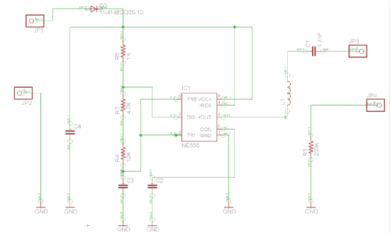
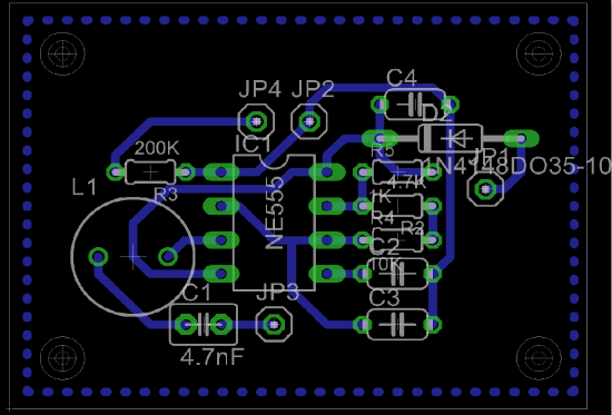
GENERATOR (for wire follower) (not realized in practice) :
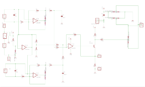
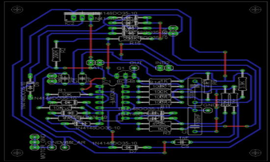
FOLLOWER SENSOR ACQUISITION (realized in practice) :
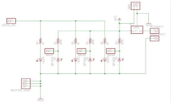
LINE FOLLOWER SENSOR ACQUISITION (realized in practice) :
REMARKS PCB PINS
Generator PCB for wire follower
-JP1, JP2 to connect the battery
-JP3, JP4 to connect the wire in which the current will flow
Wire follower sensor acquisition PCB
-MOTOR-GND: 2 pins for motor ground, 1 pin for motor battery ground
-VOLTAGE REGULATOR: from 9V of battery (greater than 7V) to 5V for the circuit
-VCC-AR: 5V to give to the arduino
-GRN-AR: ground of arduino
-IND1: pin to connect the inductance (sensor 1)
-IND2: pin to connect the inductance (sensor 2)
Line follower sensor acquistion PCB
-LED: arduino output. An Arduino wire goes there and commands if the leds are ON (5V) or OFF (0V)
-SEN1-SEN2-SEN3: sensors values to arduino inputs
-ARD: power for arduino (5V)
-VCC BATT: power of the battery (0-9V)
-GND BATT: ground of the battery