
Mechanic Design
The following part designs and assembly designs are made with the software SOLIDWORKS. Some of the parts are produced by 3D printer and thus their files are converted into *.STL which is suitable to be read by the 3D printer. The other one are produced by Laser Cutting and thus their files are converted into *.DWG, which can be used by AutoCAD.
Cover Design
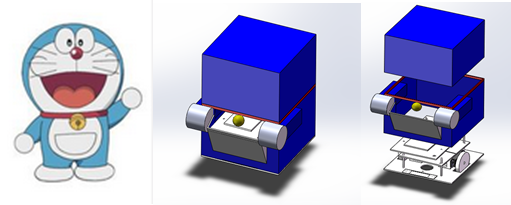
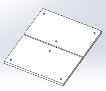
The cover of the robot is designed as Doraemon and the user can put its phone in the front pocket of Doraemon. The cover is divided into 3 parts which are Head, Body and Base Plate, so it is easy to assemble.
Head and Body Design
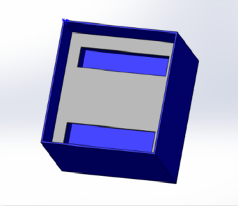
Generally Speaking, the main function of them are to work as cover to isolate the inner structure of the robot and improve the external look of it. However, for saving place in the inner space, a layer in Head is designed to install the batteries of the wheels. (Laser Cutting)
Base Plate
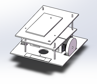
The Base Plate of the robot is crucial, the main mechanical parts and electrical parts are fixed on the plate. The following sections will detail this.
The 1st Layer
The main function of the 1st Layer is to hold the user phone, the square hole and big round hole are used for installing a button and a switch to control the 2 batteries (ON/OFF). (Laser Cutting)
The Seconnd Layer
The main function of the 2nd Layer is to fix the PCB card and the Arduino. Before installing them, suitable holes will be made by drill. (Laser Cutting)
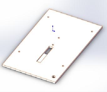
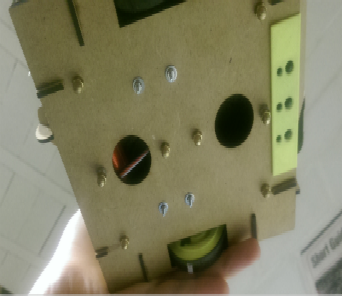
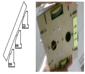
The Third Layer
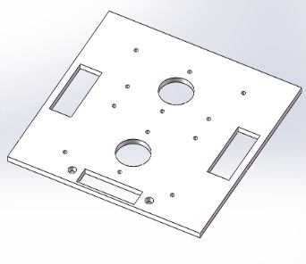
The 3rd Layer is used for installing the mechanical parts (motor bases, sensors base, supporting columns,…), The two big holes are designed for caster wheels(passive). The two square holes are for wheels and the square hole in front with two holes is used for the sensors base. (Laser cutting)
Motor Base
The motor bases are used for connecting the motors to the 3rd Layer. The four holes are to screw the motor on it and the two holes are to fit it on the 3rd Layer. (3D printer)
Sensor Base
The sensors base fits to the structure on the 3rd Layer. It is for installing sensors. Holes fitting to the sensors can be drilled on it. (3D printer)
Wheel
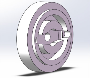
The structure of the wheels is designed for fitting the structure of the servomotors. A cycle sink is made for assembling and disassembling easily, and decreasing the stress concentration in the part. (3D printer)
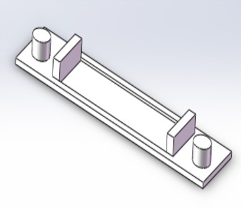
Support Column
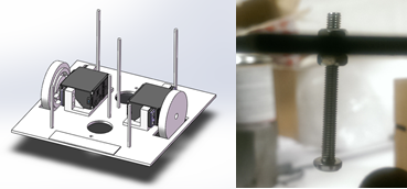
The Support Columns should be replaced by screws in practical, but because of the shortage of screw, we made screws by ourselves. The sizes of them are three M3*50mm and three M3*80mm. Two knobs can be used together to locate one light layer.
Others
Finally, caster wheels are not employed for saving money. Two knobs close to the position of the caster wheels holes are employed. The function of them are to balance the robot. The length of them have been modified to touch ground. In practice we observed only one of the knobs touches the ground during the robot move.
2D Drawing
The main things to care about when converting 3D drawings into 2D drawings are to :
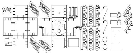
a. Pay attention on the thickness of the plate;
b. Design fitting methods;
c. Convert curve surface into flat surface;
d. Link small parts together to avoid falling into the machine after the cutting.
Following the main ideas mentioned above, the parts are converted into 2D drawin
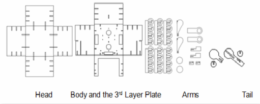
Parts for Connection
To have a light and nice looking robot, current connecting ways are employed. Parts upper are used as connecting parts.
a. Permanent Connectiong.
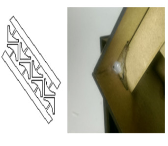
The little triangular part is inserted into the whole made by the two parts, and it is reinforced by glue.
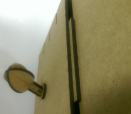
b. Temporary Connection
Those parts are just used on the 3rd Layer Plate. They are fixed on the plate. 2 parts on one side can form a surface for limiting the Body part. 8 parts can thus allow the body to perfectly fit on the layer and to be removed as wished.
Other Connection
This connection is fixed on the Body part, and it can be used to locate and fit the Head part on it.
Servomotor
Now the structure is totally designed, the mass of the robot can be approximated and the motors needed can be computed.
In order to perform the calculation of the maximum torque needed one has to know:
-The total weight of the robot
-The maximum speed that we want to reach
-The acceleration that we want for the robot to reach this speed
The equation for each motor (Newton’s second law) is:
M/r = m*a/(number of wheels) + Fr
where:
-M is the motor torque
-r is the radius of the wheel
-m is the mass of the robot
-a is the acceleration of the robot
-Fr is the friction (< 0.2*mg/2 , devided by two because there are two wheels and two motors thus)
It was asked to see if FUTUBA S3003 was ok for our application and it was. We got after inserting security factors that the torque for a motor should be of minimum 0.1 Nm when the S3003 can reach 0.3 Nm (when supplied with 4.8 V).
Moreover, one has to remove the potentiometer of the servomotors because it blocks the 360 degree motion (at the beginning it could move only of 180 degrees).
To hack the servo it is necessary to open and disassemble it (see Figure below). The potentiometer can thus be replaced by 2 resistors fixed together. It’s better to do it because one wants not only the total rotation of the wheel, but also to control the speed of the servomotor.
It is also indispensable to cut a small mechanic piece of plastic that blocks the rotation of the gears. Finally, every part is reassembled.
To see if it works or not, an arduino code is used to test the motors and to find the new offsets of the motors (see video below).
video of motor running