PCB
The printed circuit which enable to make all the electrical connections!
One of the aims of the mechatronics project is to create our own PCB for the cleaning robot. To do so the CAD Software EAGLE was used. This program allows us to make a scheme of the printed circuit board before printing it. Before making the scheme we made a list of all the functions that the microcontroller needed to fulfill:
- - Reset button
- - Power supply
- - Clock signal
- - Pin heads to load the program into the microcontroller via the Arduino UNO
- - 3 infra-red sensors data to process
- - Motor driver
- - Brushless motor controller
- - Servo motor to control
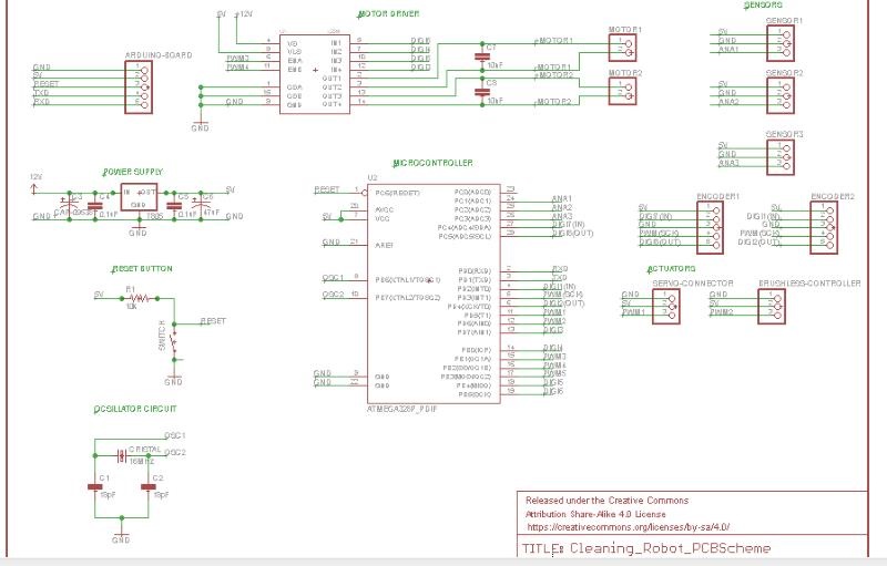
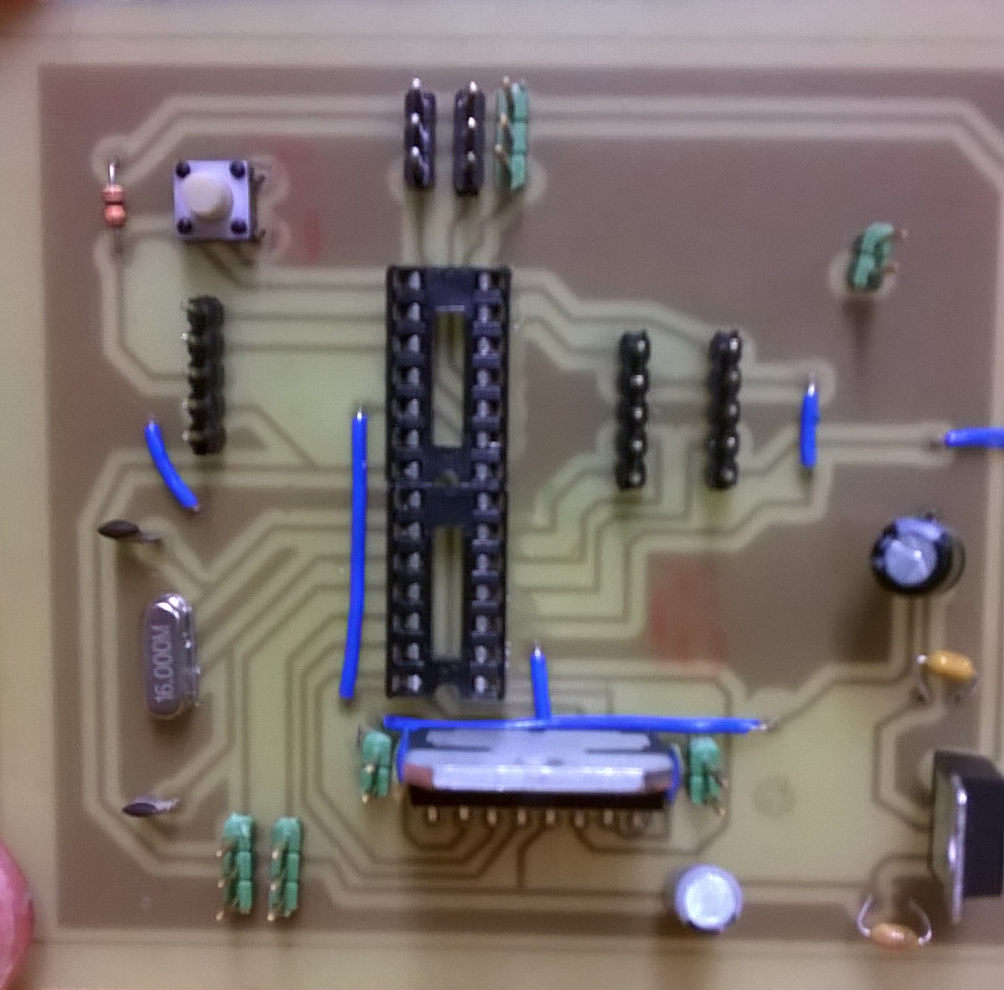
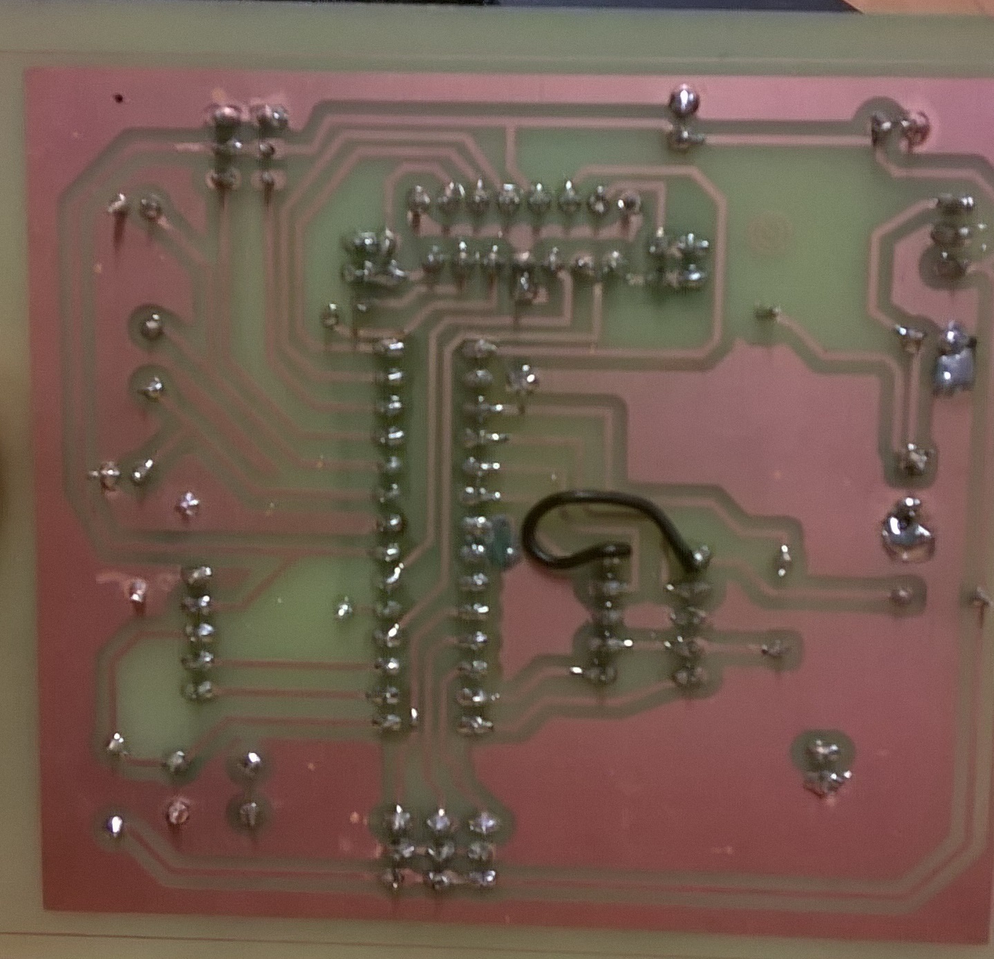
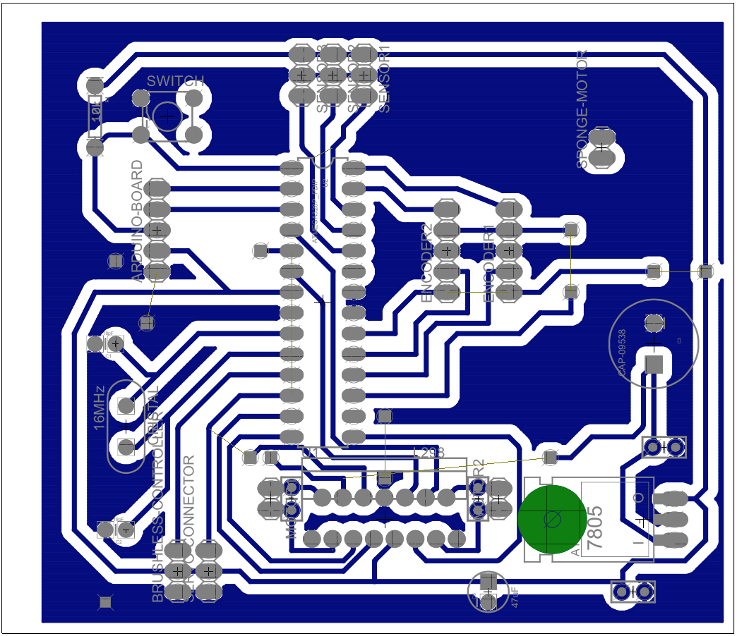
Once the schematic was ready a PCB layout was designed (connections routes have to be established in order to have the most efficient configuration). After the circuit was printed all the components were solder on it.
Computer Aided Design Software
To build this project, we had to be able to design our robot on the computer. The aim of that is to know the exact dimensions of our pieces and notice before starting the construction that things would go wrong. The program we used was INVENTOR.
FabLab
When the design on computer was done, we had to build the robot. Few years ago, the robots could be made thanks to different techniques : turning, milling, drilling. Today, the technology evolved and we used for this project laser cutting to cut our plates of plexi and 3D printing for complex pieces. The machinery was available for us at the FabLab
Eagle
The PCB is an important part of the project. It enables to connect the microcontroller with ll the different parts of the project. The creation of it requires to be precise on the band width and the place of everything. To do it, we used a program, which gather a lot of electrical components to build those boards, called Eagle