Relay
We have toys that work on 12 V AC-current and we have toys that work on DC-current. So we have to think of a circuit to let this toys work whenever we want. Firstly we were thinking of using mosfets, but we eventually didn't do it, because the mosfets works only on DC-current. And since we also have toys that operates on AC-current, this components couldn’t be used. Secondly we found optocouplers. But we didn’t found many information on it, how they operates. Also they were way too difficult. So eventually we didn’t used it. After finding this image on a site:
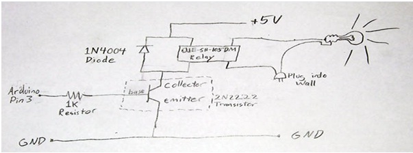
we wanted to consider a relay as a option. So we eventually have chosen to use it. On the internet we found the working principle of the relay: first it was very simple and second it was practical, since it is being used very frequently.
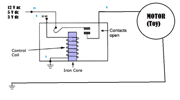
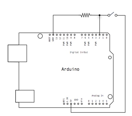
On this following schematic we see that port 6 and 2 are connected through a coil. Ports 14 and 8 are connected through a switch. So when there is 5V on the coil, there is magnetic field created. This cares that the switch between 14 and 8 are closed. If our toy is operating simultaneously (5V and toy is on), the circuit is closed and the toy is working. If there is 0V from the microcontroller, the toy won’t operate (whether it is on or not), since the contact is open.
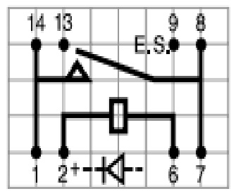
Beneath you see a schematic view of our relay that we used. Note that in the relay there is a diode parallel with the coil. This is done internally for the protection of our electrical components connected to the relay.
Switches
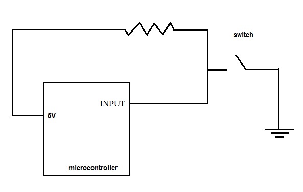
The first thing we would have thought about was the switches. On the website of the arduino we have seen the schematics of the switch.
So what we firstly did was just plug the 5V of the Arduino with the switch that we have got from Jean Paul (the technician). The output of the switch we have connected with, the ground (through a resistor), and with the input of the Arduino (channel 2). We have used a resistor of 10 kW. On the arduino there was a LED, that we controlled through this switch. We have to remark that we firstly programmed the arduino for this action. We succeeded to do it. But on the end we have noticed that we have to place a pullup resistor before the arduino. This is because we had floating. So Arduino sometimes thought that the switch is pressed, though it was not the case. With the new schematic, we have solved this problem. So we changed the schematics a little bit.
Power supply
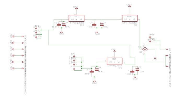
The toys we use work on 12V ac, 3V and 5V. We use the voltage converter of the disco ball. This one converts 230 V ac to 12V ac. We can directly use this voltage for the toys that work on 12 V ac. We then use a bridge rectifier to have a direct current. We now have 14 V. This tension is then converted to 12 V and then to 5 V. Here we can connect the toys that work on 5 V and the microcontroller. Finally this tension is converted to 3 V. This tension can be used to supply the toys that work on 3 V.
Microcontroller
The control of the toys happens through a simple program.
The program is built out of 2 main parts. In the first part, the ports are set to the right values and the different pins are set to be outputs or inputs. In the second part, the control mechanism is implemented.
The first part speaks for itself. Everything is initialized to the right values so that the program works in a correct manner.
The second part is a bit longer in code, so therefore we will elaborate a bit on this.
First of all, the control mechanism consists of one big infinite while-loop, where values of switches are constantly checked.
In the main while-loop, we find several smaller loops. These loops check for the following:
- Value of the LEFT/RIGHT – button
- Value of the button switch, which in this case is a foot pedal.
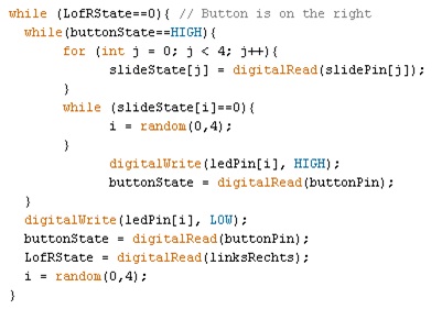
Once these values have been checked, we give the ports, in this case the toys, a high value. Since we must have the choice to turn certain toys off, an extra check must be done. This is done through another while-loop which checks the following:
- “State” of the different toys
If the “state” is turned off (LOW), the toys may not be activated through the foot pedal. If the “state” is turned on (HIGH), the toys MUST be activated through the foot pedal.
A quick look of the code is given below:
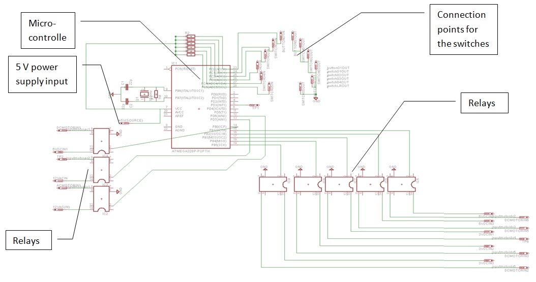
General view
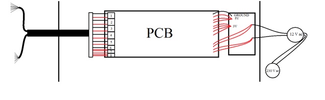
We will now assemble al the separate elements. The electronics that will convert the power to our needs are placed on one PCB and the other elements that will control the toys on another PCB. Below you can see the PCB that will control the toys.
We will connect the power supply PCB with the upper PCB. On the drawings we see that there are two wires connected to one relay. One of the wires will be connected to the 3 V, 5 V or 12 V ac power supply according to which toy will be connected to the relay. The other wire goes to the corresponding toy.
The power supply will enter the button box and will then go to a small PCB where the power supply for the main PCB and the toys will be generated. There are 2 wires entering the small PCB. The tension on these wires is 12 V AC. Coming out of the small PCB are 12 wires. One ground, four 3V wires for the 3V toys, three 5V wires for the toys running on 5V and for the power supply of the main PCB and 4 wires with a 12 V AC tension. These wires go to the main PCB. There a microcontroller controls the relays which can activate the toys. Then at the output of the main PCB there are 8 pairs of 2 wires. Each pair of wires will have to go to a toy. The Wires are then put together to be transported to the toys.