Programming
CPU
We used microcontroller MSP430F2274 to control the speed of two motors motors with respect to data from our sensors (gyroscope, accelerometer) and from an external device (pc, mobile phone) via our bluetooth module.
Structure of program
The structure of the program is described by the following picture.
Click to enlarge:
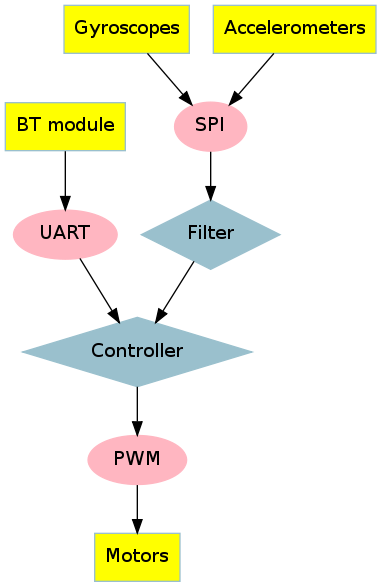
The controlling of the the trajectory of our robot is not the only application for which we use the Bluetooth module, it was also used for the debugging of the program and for showing the data of the sensors.
Realisation
Our natural approach was to program separate blocks that serve dedicated peripheries at first. The main purpose of this approach was to verify the functionality of the hardware. After that we programmed the angle filter and controller blocks. We decided to program these programs in the C-language instead of assembler. The code for the different blocks is shown in the sections below.
PWM generation:
  //////PWM outputs - P4.1-2

#include <msp430.h>


int main(void)

{

   WDTCTL = WDTPW + WDTHOLD;			// Stop WDT

   DCOCTL = 0;				// Select lowest DCOx and MODx settings /clock settings

   BCSCTL1 = CALBC1_16MHZ;			// Set DCO to 16 MHz

   DCOCTL = CALDCO_16MHZ;


   P4DIR |= 0x06;                            // P4.1 - P4.2 output

   P4SEL |= 0x06;				// P4.1 - P4.2 TBx options

   TBCCR0 = 512 - 1;				// PWM Period

   TBCCTL1 = OUTMOD_7;			// TBCCR1 reset/set

   TBCCR1 = 384;				// TBCCR1 PWM duty cycle

   TBCCTL2 = OUTMOD_7;

   TBCCR2 = 128;

   TBCTL = TBSSEL_2 + MC_1;			// SMCLK, up mode	optionaly---ID3 prescaler 8x

}
#include <msp430.h>
int main(void)
{
WDTCTL = WDTPW + WDTHOLD; // Stop WDT
DCOCTL = 0; // Select lowest DCOx and MODx settings /clock settings
BCSCTL1 = CALBC1_16MHZ; // Set DCO to 16 MHz
DCOCTL = CALDCO_16MHZ;
P4DIR |= 0x06; // P4.1 - P4.2 output
P4SEL |= 0x06; // P4.1 - P4.2 TBx options
TBCCR0 = 512 - 1; // PWM Period
TBCCTL1 = OUTMOD_7; // TBCCR1 reset/set
TBCCR1 = 384; // TBCCR1 PWM duty cycle
TBCCTL2 = OUTMOD_7;
TBCCR2 = 128;
TBCTL = TBSSEL_2 + MC_1; // SMCLK, up mode optionaly---ID3 prescaler 8x
}
SPI communication:
  //////test SPI communication with accelerometer (just for axis X)

//////slave select P2.0

//////led P4.4


#include <msp430.h>

#define TESTLED 0x08

#define CSACCEL 0x01

#define SPI_A_A_CTRL1 0x20

#define SPI_A_READ 0x80

void spiAccInit(void);

char data;


int main(void)

{

   WDTCTL = WDTPW + WDTHOLD;                 // Stop WDT

   DCOCTL = 0;                               // Select lowest DCOx and MODx settings

   BCSCTL1 = CALBC1_16MHZ;                   // Set DCO to 16 MHz

   DCOCTL = CALDCO_16MHZ;


   P4DIR |= TESTLED;                         // P4.4 output  (in case P4.5  0x10)

   P3SEL |= 0x0C;                            // P3.3,2 USCI_B0 option select

   P2DIR |= CSACCEL;                         // P2.0 output direction


   UCB0CTL0 |= UCMSB + UCMST + UCSYNC;       // 3-pin, 8-bit SPI mstr, MSB 1st

   UCB0CTL1 |= UCSSEL_2;                     // SMCLK

   UCB0BR0 = 0x02;			    //prescaled 2 times	----10MHz max communication speed for SPI

   UCB0BR1 = 0;

   UCB0CTL1 &= ~UCSWRST;                     // **Initialize USCI state machine**  -----software reset disabled

   spiAccInit();


   while(1)

   {

       P2OUT &= ~CSACCEL;                      // Enable Accelerometer

      UCB0TXBUF =SPI_A_READ + 0x29;                       // adress 29 H byte of out_X_H + READING mode

     while (!(IFG2 & UCB0RXIFG));            // USCI_B0 RX buffer ready?

        data = UCB0RXBUF;                       // data = 00|DATA

      P2OUT |= CSACCEL;                          // Disable Acceloremoeter

       P4OUT &= ~TESTLED;                         // P4.4 = 0

       if (data >= 0x7F)                       // data = AIN > 0.5(REF+ - REF-)?

         P4OUT |= TESTLED;                        // P4.4 = 1

   }

}


void spiAccInit(void){

  P2OUT &= ~CSACCEL;                      // Enable Accelerometer

  UCB0TXBUF = SPI_A_A_CTRL1;

  while (!(IFG2 & UCB0TXIFG));		//make sure that first word is away

  UCB0TXBUF = 0x39;     			 //	0b00111001 greater data rate 1000Hz only axis X enabled

  while (!(IFG2 & UCB0TXIFG));		//make sure that first word is away

}
//////slave select P2.0
//////led P4.4
#include <msp430.h>
#define TESTLED 0x08
#define CSACCEL 0x01
#define SPI_A_A_CTRL1 0x20
#define SPI_A_READ 0x80
void spiAccInit(void);
char data;
int main(void)
{
WDTCTL = WDTPW + WDTHOLD; // Stop WDT
DCOCTL = 0; // Select lowest DCOx and MODx settings
BCSCTL1 = CALBC1_16MHZ; // Set DCO to 16 MHz
DCOCTL = CALDCO_16MHZ;
P4DIR |= TESTLED; // P4.4 output (in case P4.5 0x10)
P3SEL |= 0x0C; // P3.3,2 USCI_B0 option select
P2DIR |= CSACCEL; // P2.0 output direction
UCB0CTL0 |= UCMSB + UCMST + UCSYNC; // 3-pin, 8-bit SPI mstr, MSB 1st
UCB0CTL1 |= UCSSEL_2; // SMCLK
UCB0BR0 = 0x02; //prescaled 2 times ----10MHz max communication speed for SPI
UCB0BR1 = 0;
UCB0CTL1 &= ~UCSWRST; // **Initialize USCI state machine** -----software reset disabled
spiAccInit();
while(1)
{
P2OUT &= ~CSACCEL; // Enable Accelerometer
UCB0TXBUF =SPI_A_READ + 0x29; // adress 29 H byte of out_X_H + READING mode
while (!(IFG2 & UCB0RXIFG)); // USCI_B0 RX buffer ready?
data = UCB0RXBUF; // data = 00|DATA
P2OUT |= CSACCEL; // Disable Acceloremoeter
P4OUT &= ~TESTLED; // P4.4 = 0
if (data >= 0x7F) // data = AIN > 0.5(REF+ - REF-)?
P4OUT |= TESTLED; // P4.4 = 1
}
}
void spiAccInit(void){
P2OUT &= ~CSACCEL; // Enable Accelerometer
UCB0TXBUF = SPI_A_A_CTRL1;
while (!(IFG2 & UCB0TXIFG)); //make sure that first word is away
UCB0TXBUF = 0x39; // 0b00111001 greater data rate 1000Hz only axis X enabled
while (!(IFG2 & UCB0TXIFG)); //make sure that first word is away
}
UART communication:
//////P3.4/UCA0TXD

//////19200 - 8N1

//////P3.5/UCA0RXD

#include <msp430.h>


int main(void)

{

   WDTCTL = WDTPW + WDTHOLD;                 // Stop WDT

   DCOCTL = 0;                               // Select lowest DCOx and MODx settings

   BCSCTL1 = CALBC1_16MHZ;                   // Set DCO to 16 MHz

   DCOCTL = CALDCO_16MHZ;


   P3SEL = 0x30;                             // P3.4,5 = USCI_A0 TXD/RXD

   UCA0CTL1 |= UCSSEL_2;                     // SMCLK

   UCA0BR0 = 65;                             // 16MHz 19200

   UCA0BR1 = 3;                              // 16MHz 19200

   UCA0MCTL = UCBRS0;                        // Modulation UCBRSx = 1

   UCA0CTL1 &= ~UCSWRST;                     // **Initialize USCI state machine**

   IE2 |= UCA0RXIE;                          // Enable USCI_A0 RX interrupt


   __bis_SR_register(LPM0_bits + GIE);       // Enter LPM0, interrupts enabled
}


// Echo back RXed character, confirm TX buffer is ready first

#pragma vector=USCIAB0RX_VECTOR

__interrupt void USCI0RX_ISR(void)

{

   while (!(IFG2 & UCA0TXIFG));              // USCI_A0 TX buffer ready?

   UCA0TXBUF = UCA0RXBUF;                    // TX -> RXed character

}
//////19200 - 8N1
//////P3.5/UCA0RXD
#include <msp430.h>
int main(void)
{
WDTCTL = WDTPW + WDTHOLD; // Stop WDT
DCOCTL = 0; // Select lowest DCOx and MODx settings
BCSCTL1 = CALBC1_16MHZ; // Set DCO to 16 MHz
DCOCTL = CALDCO_16MHZ;
P3SEL = 0x30; // P3.4,5 = USCI_A0 TXD/RXD
UCA0CTL1 |= UCSSEL_2; // SMCLK
UCA0BR0 = 65; // 16MHz 19200
UCA0BR1 = 3; // 16MHz 19200
UCA0MCTL = UCBRS0; // Modulation UCBRSx = 1
UCA0CTL1 &= ~UCSWRST; // **Initialize USCI state machine**
IE2 |= UCA0RXIE; // Enable USCI_A0 RX interrupt
__bis_SR_register(LPM0_bits + GIE); // Enter LPM0, interrupts enabled }
// Echo back RXed character, confirm TX buffer is ready first
#pragma vector=USCIAB0RX_VECTOR
__interrupt void USCI0RX_ISR(void)
{
while (!(IFG2 & UCA0TXIFG)); // USCI_A0 TX buffer ready?
UCA0TXBUF = UCA0RXBUF; // TX -> RXed character
}
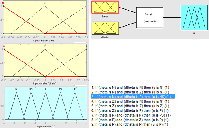
Control Algorithms
We implemented a fuzzy control strategy to balance our Wheeled Inverted Pendulum. We use the angle and the angular velocity together with the shape functions and control rules (see figures below) to produce an output.
Complementary filter
The fuzzy control algorithm uses the angle and the angular velocity as input parameters. To get an accurate estimation of the angle and angular velocity of our Wheeled Inverted Pendulum, we need to filter the data from our sensors. Our IMU (inertial measuring unit) contains a gyroscope and an accelerometer. The accelerometer senses the angle (using 2-axis method), while the gyroscope senses the angular velocity. However, the readings from these sensors can contain alot of noise. We try to reduce the noise using the simple complementary filter, shown in the figure below:
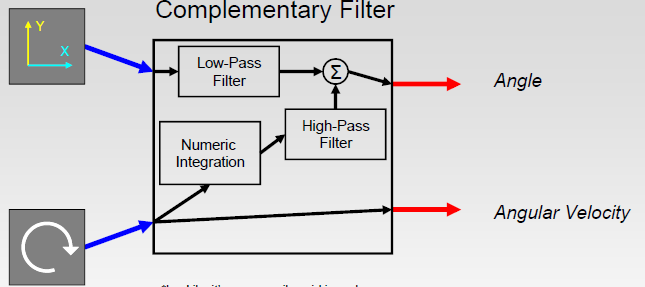
An alternative for the complementary filter is famous Kalman filter. We prefered to use this filter, because of it's simplicity and no need for complex mathematical models needed by a Kalman filter. The complementary filter uses the noisy data of both sensors and combines them in a way to provide a better estimation of the angle.
As can be seen in the picture above, the angle output from the accelerometer is filter by a low-pass filter, so only long-term changes have an effect on the filtered angle, thus filtering out short-term fluctuations. This is to filter out the movement acceleration of the robot itself, which also gets picked up by the accelerometer.
The accelerometer data is used directly to estimate the angular velocity. However, it is also used to correct the angle measured by the accelerometer, by integrating the angular velocity. The integrated value is passed trough a high-pass filter, so only short-lasting fluctuationgs have an effect.
Matlab aplication
We also developed a grafical user interface. The first purpose was to better identify our system, to improve the control agoritm. The second purpose of this graphical aplication is that it may work as a simple joystick for controlling the trajectory of our robot.
Click to enlarge:
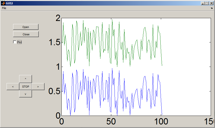
This GUI is based on the following code. It reads messages of 12 bytes from the serial port where the Bluetooth module is connected, identifies if the message is correct with the use of a header and a tail for the message and plots the values from the message to a chart. The code for the GUI is shown bellow:
Open serial port:
    sport=serial('COM9','baudrate',9600);

fopen(sport)
fopen(sport)
Plotting part:
    tail=[1,16,1,16]';

head=[240,15,240,15]';

tic

while sport.BytesAvailable

     message=fread(sport, messagelength);

     if (message(1:4,1)==head(:,1))&(message(17:end,1)==tail(:,1))

           signalvector=message(5:16,1);

     else

           signalvector=zeros(12,1); %consider taking of last sample

           for i=1:messagelength-4

     	if(message(i:i+3,1)==head(:,1))

        fread(sport,messagelength+i-1)

        break

     	end

      if(message(i:i+3,1)==tail(:,1))    %synchronise

        fread(sport,i+4-1);

        break

       end

    end

     end

     plotsignals=[plotsignals(:,2:end) signalvector];

     timeaxis=[timeaxis(:,2:end) toc];

     plot(timeaxis', [plotsignals; Availablebits]')

     axis([timeaxis(1,1) timeaxis(1,end) 0 3000])

     drawnow

end
head=[240,15,240,15]';
tic
while sport.BytesAvailable
message=fread(sport, messagelength);
if (message(1:4,1)==head(:,1))&(message(17:end,1)==tail(:,1))
signalvector=message(5:16,1);
else
signalvector=zeros(12,1); %consider taking of last sample
for i=1:messagelength-4
if(message(i:i+3,1)==head(:,1))
fread(sport,messagelength+i-1)
break
end
if(message(i:i+3,1)==tail(:,1)) %synchronise
fread(sport,i+4-1);
break
end
end
end
plotsignals=[plotsignals(:,2:end) signalvector];
timeaxis=[timeaxis(:,2:end) toc];
plot(timeaxis', [plotsignals; Availablebits]')
axis([timeaxis(1,1) timeaxis(1,end) 0 3000])
drawnow
end
Close serial port:
    fclose(sport)

delete(sport)
delete(sport)
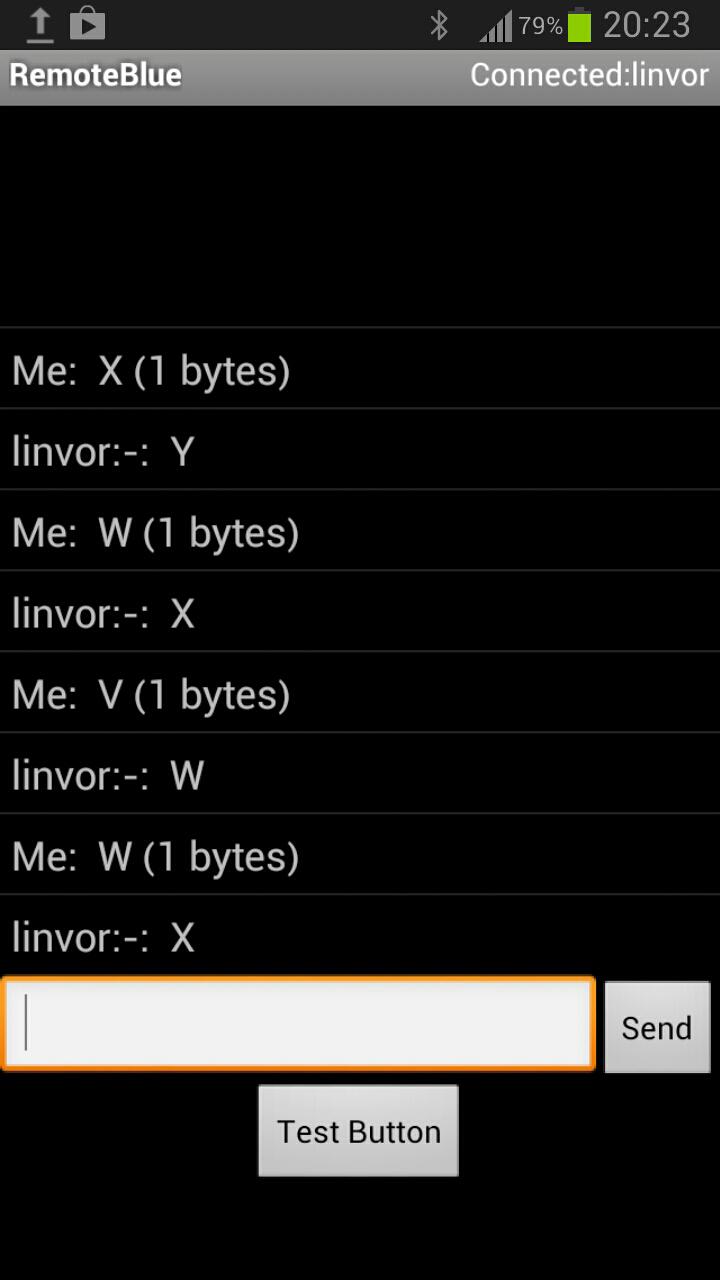
Android application
We also designed a simple java aplication for the control of the trajectory of our robot.
This application allows the same controlling functionality as the Matlab graphical user interface. For developing we used standart Android libraries for bluetooth communication android.bluetooth and android.hardware for mobile device accelerometer sensors.
Like in Matlab GUI this aplication sends single control character.
Symbol |
Meaning |
F |
Forward |
B |
Back |
L |
left |
R |
Right |
S |
Stop |
Unlike in matlab code it is not necessery to push buttons for control. Control character is send when value of mobile device accelerometer (pose of mobile phone) overcome given treshold. It is also possible to write symbol manually. It is usable for next developement.
Nevertheless at this moment the application provides very rough control. Future improvement is possible and desired.
Click to enlarge: