The checkers algorithm and the image processing is working through code written in Matlab. The main file of the checkers robot can be seen below, we will not bore you with the code of all the inner functions of the program on the website. How the most important parts work is explained below.
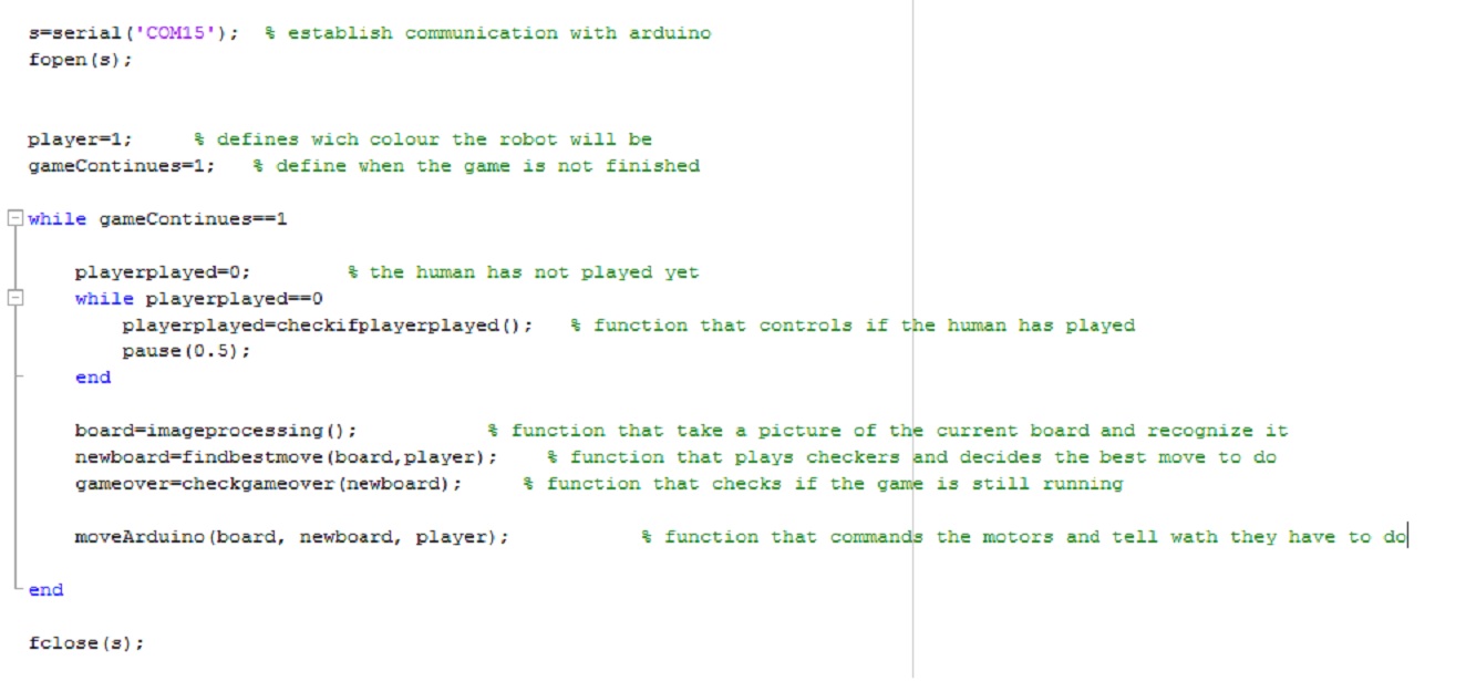
When the program enters the main loop, the first thing it will do is wait until the human player has played. This is done thanks to image processing, the program checks if there is a hand on the board, it is easy to recognise thanks to the colour of human skin.
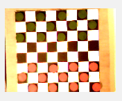
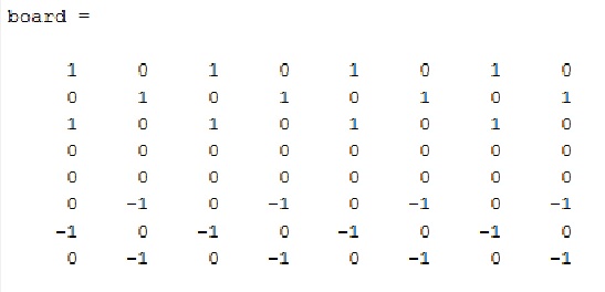
When the player has played, the function “imageprocessing()” will return an 8X8 matrix with on each cell a number: “0” if there is nothing, “1” if there is a green peace and “-1” if there is a red peace. The working of this function is simple, the program checks the colour of the pixel in the middle of each cell and recognizes if there is a piece. For example with this picture:
The program will return this:
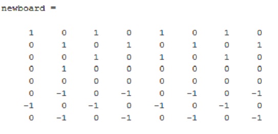
When the robot knows how does the board looks like, it can decide which move it will do. This is done thanks to the function “findbestmove(board,player)”. This function returns how the board will look like once the robot will have played. This is the most complicated part of the program, it has to decide which is the best move that the robot can do. The robot checks all different possibilities and anticipates every combinations 5 turns in advance. So it can decide which move will be the most profitable.
In the example above, the function would return this:
If the program could not do any move, it would mean that the game is finished and the function above would return an 8X8 matrix with only zeros. So the next function controls that it is not the case.
The next function is the function “ moveArduino(board, newboard, player)”. This is the function that gives the orders to the Arduino micro controller. By comparing the current board configuration and the new board configuration it will see which piece has to moved and where. The angles of each servomotor of the robots arm are calculated in function of the coordinates of the pieces that have to be moved. Once everything is calculated, the matlab code sends 4 angles to the Arduino for each move. It gives the necessary information to say to the robot where is the piece that has to be moved, and where that the piece has to be moved.
The robot is controlled by a microcontoller running Arduino. When Matlab calculated the best move, the move need somehow to be excecuted by the robot. To pass the information between the computer and the robot we use serial communication.
Below is the used Arduino code with some explanation
#include <Servo.h>

// create servo object to control a servo
Servo servo1;
Servo servo2;
Servo grabber;
//inital position of motors and leds
int openPosition;
int closedPosition;
int led1=3;
int led2=2;

String readString, stringS1A1,stringS2A1,stringS1A2,stringS2A2;

void setup()
{
  // attaches the servos on the pins
  servo1.attach(10);
  servo2.attach(11);
  grabber.attach(13);
  //attaches leds to pins
  pinMode(led1, OUTPUT);
  pinMode(led2, OUTPUT);
  //start serial communication
  Serial.begin(9600);

}
 //function to move the arms to desired angels
 //with code that makes the arms move slow to have better controll
void moveToAngles(int endAngle1, int endAngle2)
{
  digitalWrite(led1, HIGH);

  int waitTime=20;
  int angle1=servo1.read();
  int angle2=servo2.read();

  while(angle1 != endAngle1 or angle2 != endAngle2)  //move until desired position is reached
  {
    if(angle1 < endAngle1)
    {
      angle1=angle1+1;
    }
    else if(endAngle1<angle1)
    {
      angle1=angle1-1;
    }

    if(angle2 < endAngle2)
    {
      angle2=angle2+1;
    }
    else if(endAngle2<angle2)
    {
      angle2=angle2-1;
    }
    delay(waitTime);
    servo1.write(angle1);
    servo2.write(angle2);

  }
}
// open or close the grabber
void moveGrabber(int endAngle)
{
  int waitTime=30;
  int angle=grabber.read();

  while(angle!=endAngle)
  {
    if(angle<endAngle)
    {
      angle=angle+1;
    }
    else if(endAngle<angle)
    {
      angle=angle-1;
    }
    grabber.write(angle);
    delay(waitTime);
  }
}

void grabPiece()
{
  moveGrabber(openPosition);
  moveGrabber(closedPosition);
}

void releasePiece()
{
  grabber.write(closedPosition);
  grabber.write(openPosition);
}

void loop()
{

  while(Serial.available()==0) //fill the buffer until all data is captured
  {};

  while (Serial.available())
  {
    delay(3);  //delay to allow buffer to fill
    if (Serial.available() >0)
    {
      char c = Serial.read();  //gets one byte from serial buffer
      readString += c; //makes a long string of all the data in buffer ==> readString
    }
  }

  if (readString.length() >0)
  {
    stringS1A1 = readString.substring(0, 3); //get the first 3 characters
    stringS2A1 = readString.substring(3, 6); //get the 2nd 3 characters
    stringS1A2 = readString.substring(6, 9); //get the 3rd 3 characters
    stringS2A2 = readString.substring(9, 12); //get the last 3 characters
    readString="";                            //empty the readString

    // converts string into number
    int servo1Angle1 = stringS1A1.toInt();
    int servo2Angle1 = stringS2A1.toInt();
    int servo1Angle2 = stringS1A2.toInt();
    int servo2Angle2 = stringS2A2.toInt();

   // move to the piece that should be moved
    moveToAngles(servo1Angle1,servo2Angle1);

    //grabs that piece
    grabPiece();
    delay(2000); //delay to finsh the moves

    // move the arm with the piece to the new positon
    moveToAngles(servo1Angle2,servo2Angle2);

    //realease the piece
    releasePiece();
  }

}
The arduino code is actually a loop that never stops. The loops checks for incoming data from the serial communication and when data is receved the program really start to run.
We know that the incoming data always will be a string of 12 bytes from the computer, where every three bytes represent a positon for a servo. The first six tells where the arms should pick up the piece and the last six where to drop it.
As we know that, it's easy to divide and attach the right position to the right servo. When that is done the algorythm just make sure that the right move is made in the right order.
The speed of the servos is slowed down to have smoother and mor controlled movements.