Hand Training Robot
Bruface Mechatronics Team Project

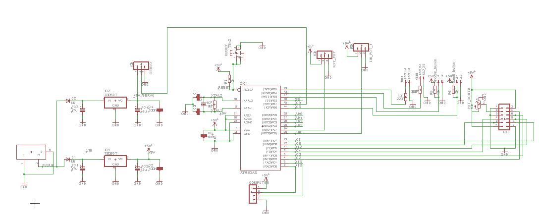
First, we just wanted to program on an Arduino Uno to command our device. But since we didn’t want to put an extra box on a side and it didn’t fit inside the main piece of the system, we decided to design a custom PCB that would be able to control everything. Indeed, we didn’t need every components of the Arduino and we just took the bare necessities to put on a PCB adjusted to the dimensions of the device.
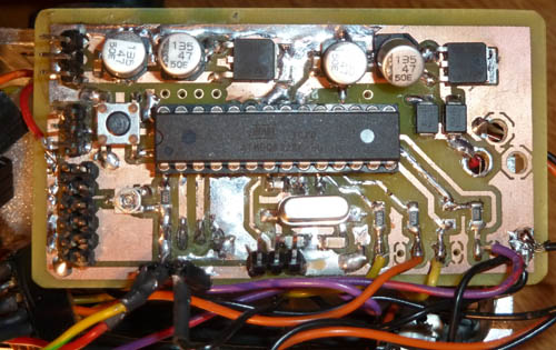
Here after you can see the final PCB with the legend of all the components we used:
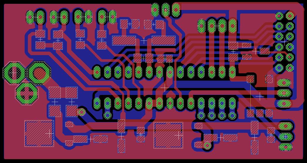
| 1 | Input power supply 12V | Used for the initial 12V supply of the PCB |
| 2 | Resistors 270 Ω | To limit the current of the LEDS |
| 3 | Resistor 10 kΩ | Essential for the utilization of the choose button |
| 4 | Input for button | To connect the choose button that validates the choices of the user near the LCD on the top of the device |
| 5 | Output to the joystick | To have a connection to the joystick when we press the handle for the Video Game mode |
| 6 | Output for LED 5mm | To connect the green LED 5mm for the Reflex mode |
| 7 | Output for LED 3mm | To connect the red LED 3mm that shows that the device is connected and ready to be used |
| 8 | Quartz 16MHz | Mandatory for the µC to have a clock for its time basis |
| 9 | Capacitors 22pF | Mandatory for the use of the clock of the µC |
| 10 | Input for linear potentiometer 50 kΩ | Connected to the handle to show its position to the µC |
| 11 | Resistor 1 MΩ | Mandatory for the use of the clock of the µC |
| 12 | Capacitor 100nF | Mandatory for analogical signals and a good alimentation of the µC |
| 13 | Output for communication with computer | To connect the µC to the Arduino connected to the computer to program the µC |
| 14 | Resistor 10 kΩ | Essential for the use of the reset button |
| 15 | Potentiometer 10 kΩ | To settle the contrast of the LCD display |
| 16 | Ouput for LCD display | To easily connect all the wires of the LCD display to the PCB |
| 17 | Input for rotational potentiometer 10 kΩ | To say to the µC the parameters chosen by the user |
| 18 | Reset button | To reset the PCB |
| 19 | Output for servomotor | To connect the alimentation and the command of the servomotor |
| 20 | Capacitor 100 nF | Essential for the 5V supply needed by the PCB |
| 21 | Capacitors 47 µF | Essential for the 5V supply needed by the PCB |
| 22 | Transistor 7805DT | To regulate and transform the 12V into 5V needed for the PCB |
| 23 | µC ATMEGA8 : AT90S4433P | To command and receive information of all the components connected to the PCB |
| 24 | Capacitor 100 nF | Essential for the 5V supply needed by the PCB |
| 25 | Capacitors 47 µF | Essential for the 5V supply needed by the PCB |
| 26 | Diode rectifier M7 | Essential for the transformation from 12V to 5V |
| 27 | Transistor 7805DT | To regulate and transform the 12V into 5V needed by the PCB |