Hand Training Robot
Bruface Mechatronics Team Project

This page presents the different electronics components of our robot which constituted the in- and outputs of the PCB (the components of the PCB are detailed in the page ‘µP’). Lots of the them have been salvaged from previous projects.
These components are classified in functional order: those for the interaction with the user, those for the feedback signals required to control the system and the last one for the motion of the mechanical parts.
On/Off LED
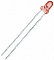
A classic red 3mm LED is used to inform the user when the device is powered. It is placed in a hole of the mechanical box for sake of visibility
Reflex LED
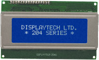
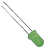
In the Reflex mode, a random signal from the microprocessor flashes on and off this green 5mm LED. This LED is placed close to the LCD screen.
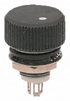
Choice Rotational Potentiometer 10kΩ
In general, a potentiometer is a rather basic component. It has three identical connections: V_cc, GND and signal, where the signal returns a value between GND and V_cc in linear accordance to the position of the cursor for a linear potentiometer and of the angle of the wheel for a rotational one.
This rotational potentiometer returns the signal value chosen by the user that allows the parameter settings. It is placed on the right of the LCD screen to benefit of an easy use.
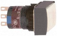
Select Push Button
It has two connections with the PCB. This button is active at low state, i.e. when the button is pushed, the microprocessor detects a voltage of 0V and interpreted this via the uploaded code: it selects the data that are chosen by the user. This push button is placed just below the rotational potentiometer.
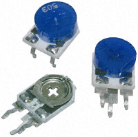
Contrast Potentiometer 10kΩ
This potentiometer, included on the PCB, works according to the same principle than previously and is used for the LCD contrast setting.
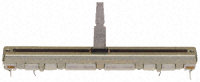
Grip position Linear potentiometer 50kΩ
Another linear potentiometer is used in our device. Its value is 50 kΩ and it is 6 cm long to perfectly fit with the stroke of the handle. It is directly connected to the handle we press to allow us to know the exact position of the handle according to the instruction it sends to the PCB. Thanks to that, we can know if the user pressed the handle correctly or if the exercise is not validate. Moreover, it is represented as a progress bar on the LCD display.
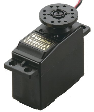
Servo Linear potentiometer 10kΩ To change the difficulty of the exercises, we used a screw connected to a servomotor futaba s3003. When it rotates, it increases or decreases the level depending on the direction in which it turns.
To do so, we first had to transform our servomotor to obtain a continuous rotation. So we cut the pin on the gear that prevented that, and then we removed the rotational potentiometer present on the servomotor. As a matter of fact, this potentiometer gave the angle the motor had to rotate. But in our case, what we are interested in is the position of the base of the springs to act on the spring rate. So, we connected the connections that were on the basis rotational potentiometer on a linear potentiometer (its value is 10 kΩ) related to the base of the springs to define the level the user had chosen. Thanks to that mechanism, the servomotor rotates until the linear potentiometer reaches the set-point he received.