


HARDWARE
The complete circuit was finished after testing all the components, this was done to easily detect the mistakes. To make the printboard we used the program TraxMaker. This program is easy to use, and the used components were already in the library and could be imported easily. Downhere you see the printboard in TraxMaker.
The stabilisated source:
The source was a package of 10 cells of Cadmium-batteries ( 12 V ). The most controllers and chips need a stabilized source of 5 V, so we used a LM7805. This chip provides a 5 V voltage source.
The microcontroller
We used the PIC16F873A. On the next picture you see the PIC-microcontroller and all the pins with their meaning.
In order to have a good functioning, we have to connect some extern circuits and components on the µC. All the controllers make use of a certain clockfrequency delivered by an oscilator cristal. Here you can see the circuit:
The microcontroller is a programmable component, so we have to make a circuit to reset the loaded program.
To load the program we used In-Circuit Serial Programming. The circuit is shown on the next picture.
Motor
The DC-motors are speed-dependent, depending on the applied voltages ranging from 0 to 12 V. The reason why the motors weren't driven directly by the microcontroller is because the voltage was to loow and the needed power couldn't be provided. To solve this, we used a H-bridge that works with simple digital logics. The H-bridge is a L6205D chip, this chip is very compact. We have two motors so we need 2 bridges, the advantage of this chip is that these two bridges are integrated in it. Below you can see the circuit with the needed components and values that are needed to build the bridge.
Sensors
We used the next sensors:
3 sharp IR-sensors: these sensors detect an object and depending on the distance there is a representative voltage. These sensors need a source of +5V.
The IR-sensor: we used this sensor to detect the flame. When the sensor detects the flame this sensor gives a low signal. This sensor also needs a +5V source.
The Tracker-sensor: these sensor is used to track a line and to folow it. This sensor also needs a +5V source.
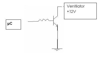
Fan
The fan was controlled with a logical switch. This switch was made with a bipolar transistor. The emittor was grounded. When the signal from the controller is low, there is no voltage over the base pin and there won't be a base current and also no emitter current. Because the collector current is quasi equal to the emittor current, there will flow no current to the fan.When the signal is high, there will flow a base current and also a collector current, so the fan will work. The resistance was found experimentaly and the value of it was 10kOhm.
Last Update: 21/05/2008 14:49