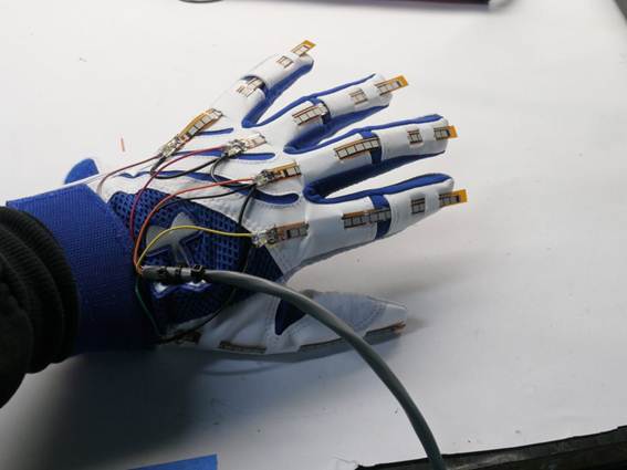
The first function that our device needs to pursue is detecting the movements of all fingers belonging to the person wearing the control
glove; to do this, Flex Sensors are used: Flex Sensors are particular kinds of potentiometers which are able to capture the displacements
of a component. In our case, we have five Flex Sensors placed on a control glove, one over every finger; all these sensors are then connected
to the PCB by means of a cable containing all their electrical wires. Also, the control glove chosen by us has an average-large size,
and it is made in an elastic material, so that most people can be able to wear it.
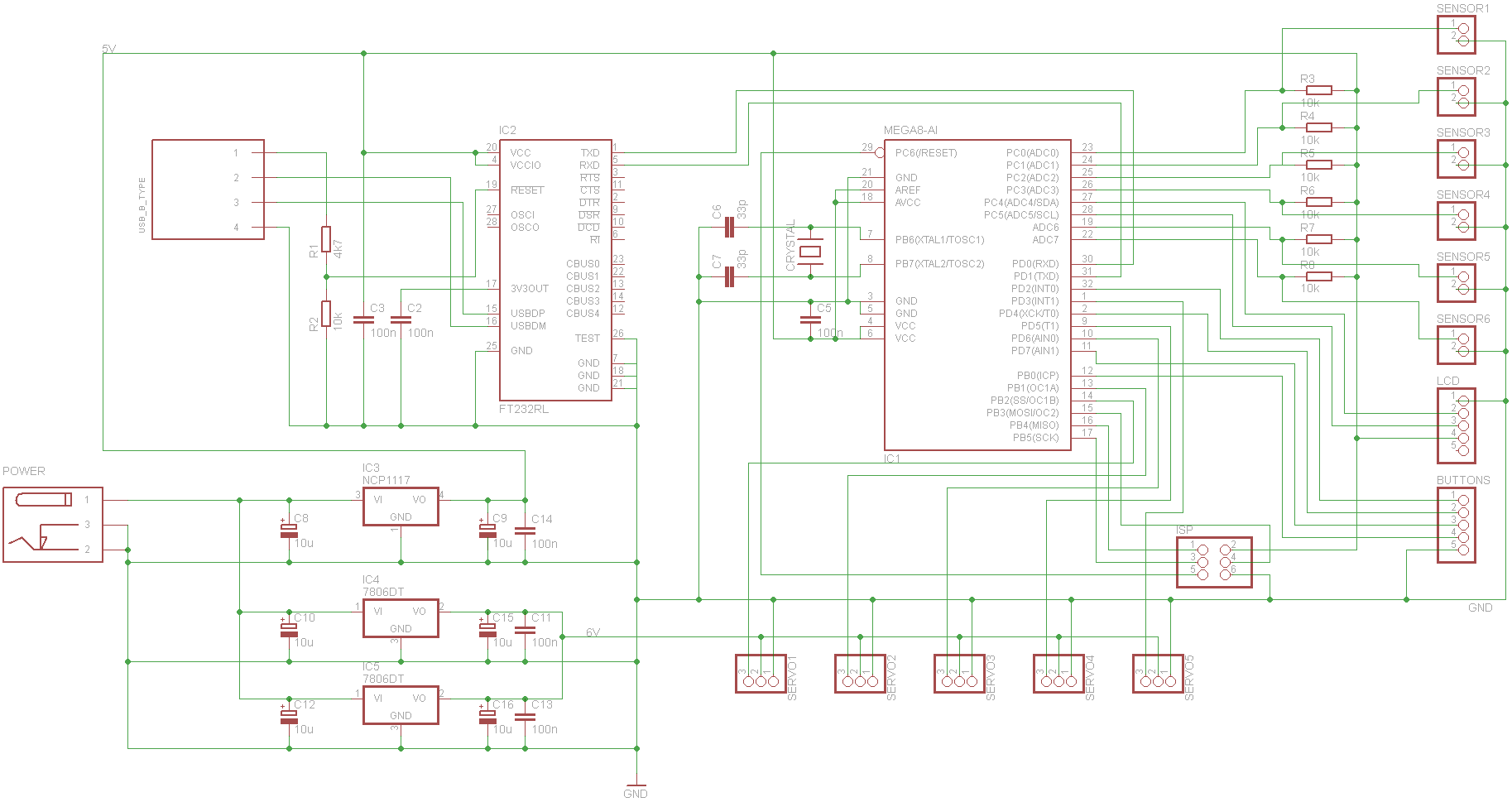
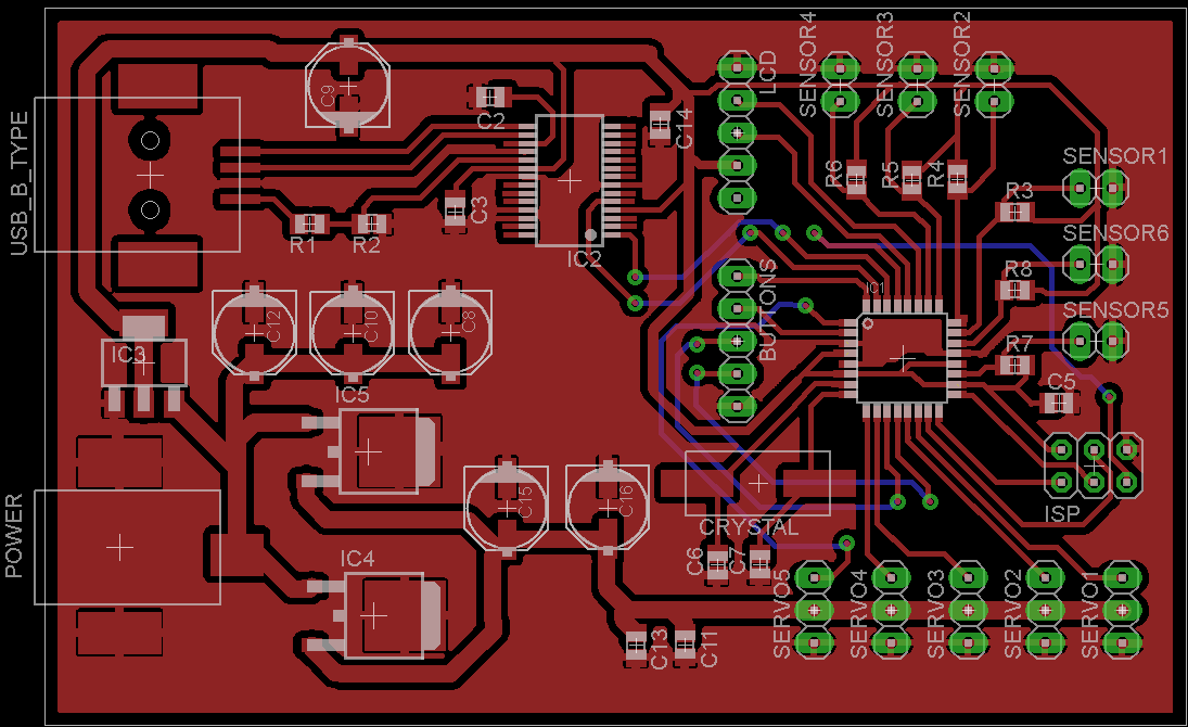
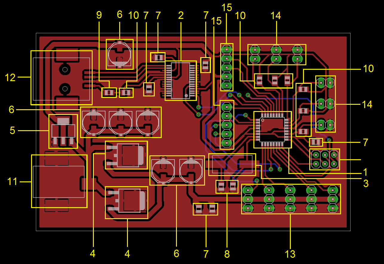
PCB
The dedicated design of the PCB ensures the information flow and the power supply of the device.
The flex sensors have a working principle of a potentiometer. Each of them is connected via the determined pin header to
the PCB. To be able to gather information, there is a voltage divider structure on the PCB. With the acquired information
the micro controller is able to control the connected servomotors. For rapidity and precision an external clock is used for the
microcontroller. The PCB is powered by an external power supply. As the servos run with a voltage of 6V in order to obtain
higher speed and the microcontroller runs with 5V, the PCB features two power circuits which are realized by using different
voltage regulators. There are several programs running on the microcontroller in order to conduct different tests. For future
needs the program structure might be changed or expanded. Therefore the USB interface guarantees an easy change of programs on
the microcontroller. Nevertheless there is still the possibility of using an in-system programmer, as you need the ISP interface
anyway to burn the boot loader on the microcontroller. All external modules like the LCD or the board containing the buttons, are
connected via pin headers and can be removed or replaced easily. The LCD provides the user of the device with necessary information
about the program, while the buttons are used to switch between programs or to adjust a parameter that is used in a program.
We report in the table below the list of the components that have been put on our PCB, with a reference number recalling the image shown in the series above: