TEAM1 - Project - Brachiationbot - 2012-2013
SWINGING
On this section, you will find :
Firstly, the natural behaviour.
Secondly, a swinging without regulation.
Thirdly, a swinging with regulation.
Finally, the use of a inclined ladder used during the test.
The study below was done by taking into account the data and requirements from the specifications section and the mechanics section.
1. Natural behaviour
The Video 1 below is a simulation of the swinging of the robot by implementing and using the parameters from the code of a PhD Japanese report (the report can be downloaded here).
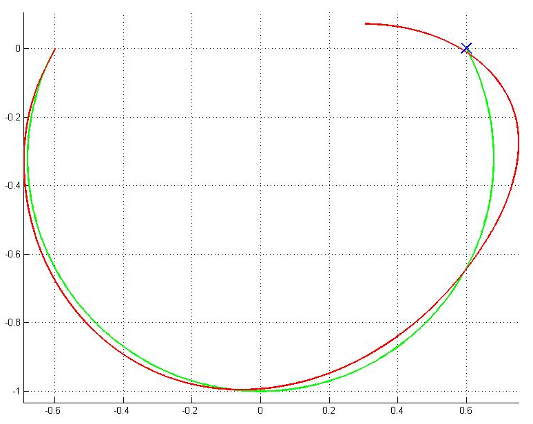
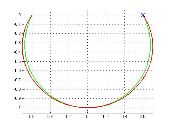
The Figure 1 below represents the simulated (red curve) and the desired (green curve) paths.
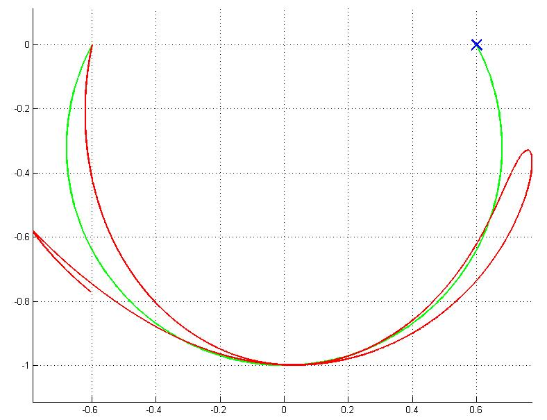
We notice that the free arm could reach the next limb with the help of a servomotor which can supply the required torque and speed at a particular position angle.
The servomotor has to be carefully programmed in order not to get a loss of swinging.
The programming of this servomotor is dealt with at the Electronics section.
Before programming the servomotors, we have to decide what is the function of the servomotors for our robot. This study was done in the below subsection by taking into account
the datas and requirements from the Specifications section and the Mechanics section.
2. Without regulation
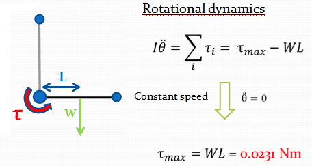
By using the simulation and the rotational dynamics equation we computed the maximum torque which is equal to 0.0231N.m (see Figure 2)
and a speed equal to 80rpm (see Figure 3).
These values allows us to choose a servomotor and sensor with a reasonable cost.
The speed regulation is constant.
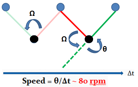
The idea of Figure 3 was that MATLAB evaluated the time in which the black ball reached its maximum height by holding the omega angle constant. Then, we computed the theta angle (by means of trigonometry properties) that the green leg has to do in order to catch the next limb. By dividing the theta angle by the time, we obtained the angular speed value that the servomotor has to be able to supply.
3. With regulation
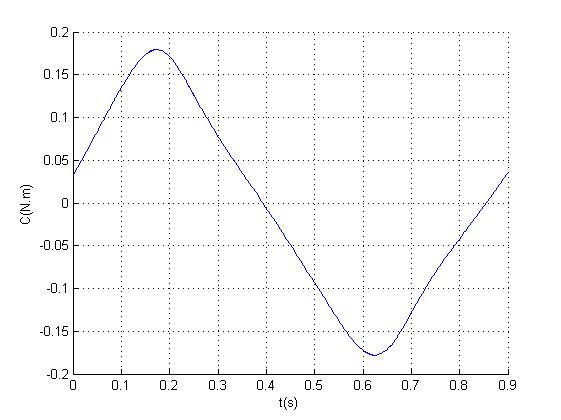
To perform this regulation, a servomotor at the elbow is needed. The following regulation is a proportional one where a computed sinus is the tracked reference. The following idea is to play with the inertia and the swing of the robot.
3.1. PD regulation
The implementation of a proportional-derivation regulator in MATLAB was suggested in order to solve the problem, as shown in the Video 2 below.
However, this process led us to look for a servomotor with a high torque estimated at 0.85N.m (see Figure 5) and also to be able to supply a high angular velocity at 275rpm (see Figure 6) for an arm with 10cm length (which is the required value length with respect to the detail design part, see Mechanics section). This kind of servomotor is very expensive.
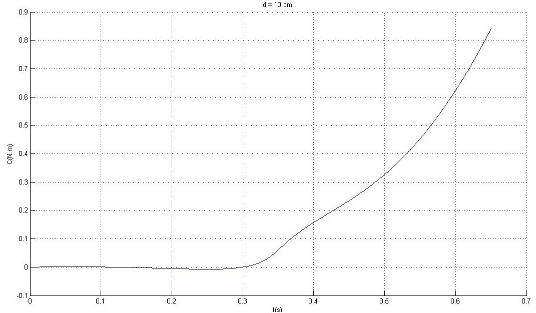
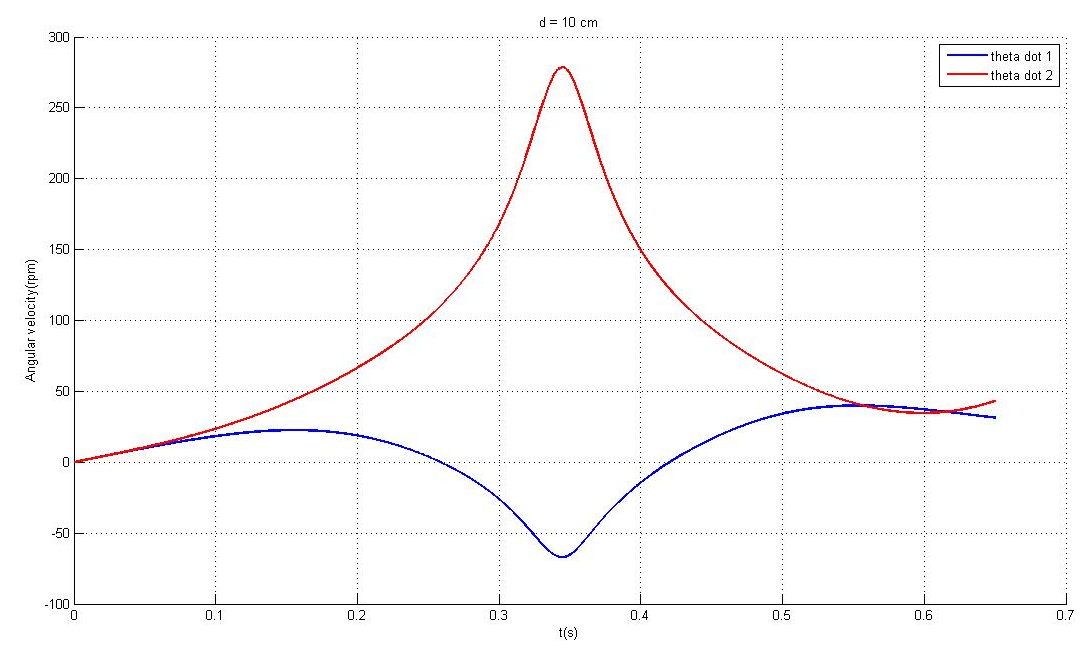
We noticed on the Figure 6 that the angular velocity of the pendulum arm was decreasing (blue curve) while the other one was increasing (red curve) from the starting point. When both arrived at their minimum height, the deceleration of pendulum arm reached the maximum and the acceleration of the other arm reached the maximum as well. Then, the pendulum arm was pulled up by the second arm which started to decrease its acceleration.
3.2. Target dynamic controller
Another method to solve the problem was to use a controller from the PhD Japanese report (here) whose principle was to control the angular acceleration by adjusting the torque. Once implemented it in the MATLAB software and adapted it to our project (the code can be downloaded here), we were led to look for a less torque value (see Figure 7) and to get a better control system than the PD controller (see Figure 8), but it demands a very large power of calculation that the Arduino can not supply.
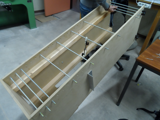
4. Inclined ladder
During the test (see the Assembly section), the main servomotor (responsible for rotationg between two arms) was broken and the servomotor of one of two grippers was damaged significantly. Because there was only one motor, we saw that there was a back-reaction of the arm. So, in the end, an inclined ladder (see Figure 9) was used instead and the main servomotor was taken off.