Troubleshooting

In this section the encountered problems and the solution we found are described.
Problem 1
Due to the quite complicated design of our eye-module we encountered several problems when assembling the different parts and trying to get them working.
Originally the whole eye-module was made of plastic printed with the Dimension 3D printer and supposed to work with strings to transfer the movements between
the motors and the different parts.
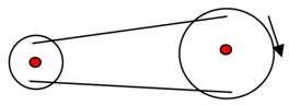
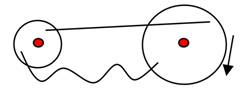
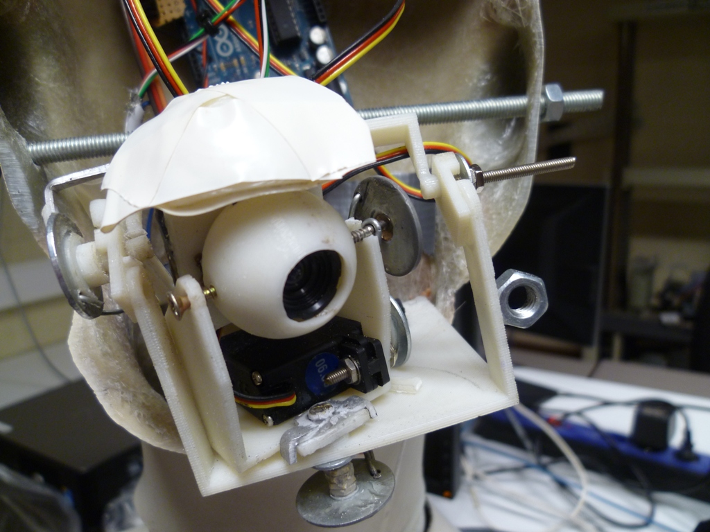
Those strings quickly revealed weaknesses. The wires were stretched only when you pulled in one direction but loosened the other way because gears had not the same size at both sides of the transmission. One side of the transmission was on the motor and the other one on the eye-ball to rotate it. We quickly realized this was not a good solution because it was not rigid enough. Also the knots loosened with time creating slack which meant we could not control the motors precisely. This is shown by the images below:
Solution 1
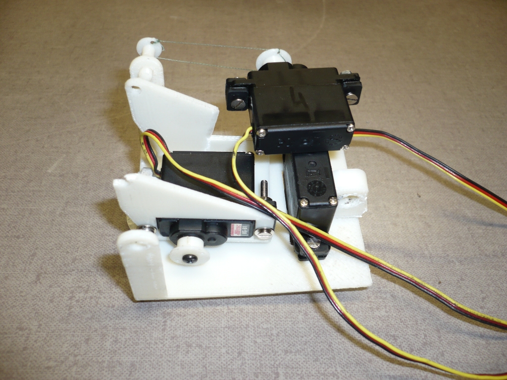
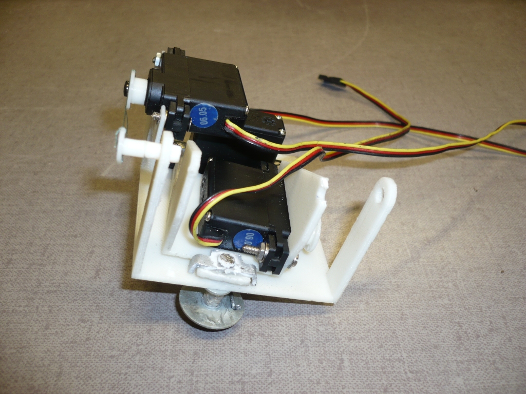
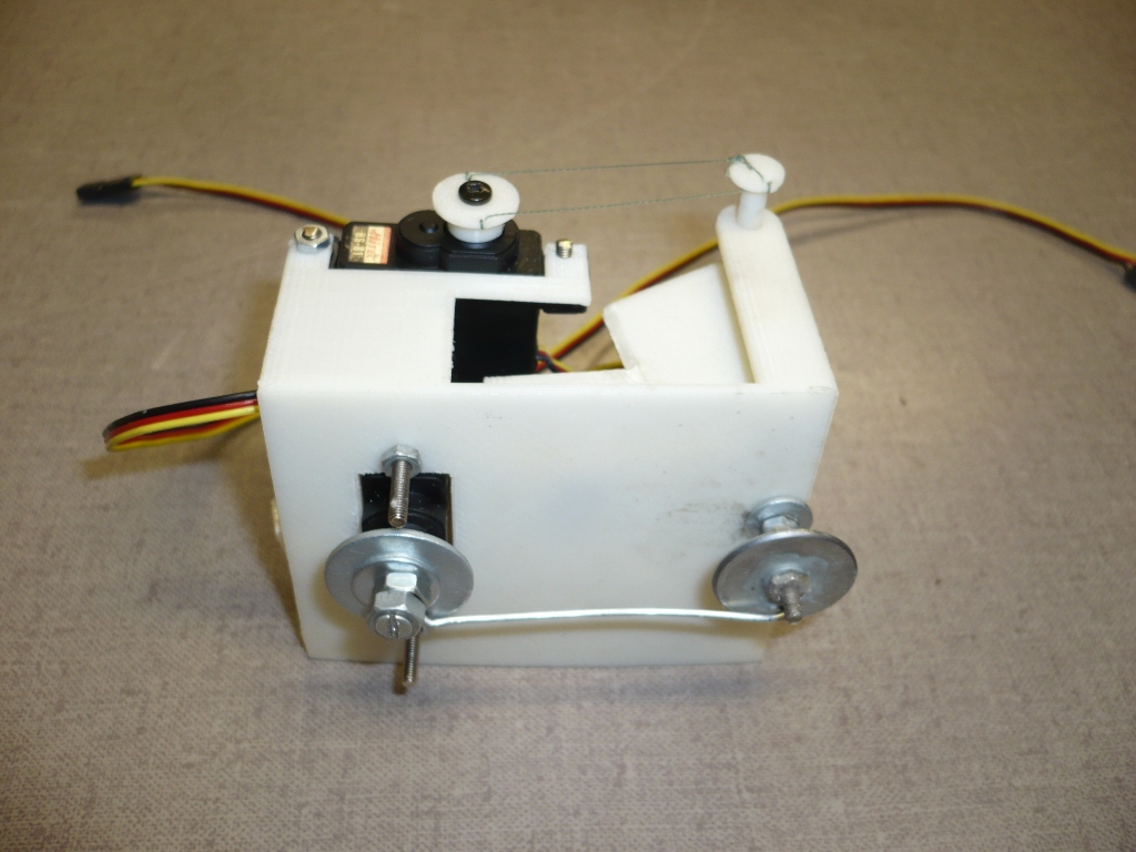
The difference in transmission ratio was resolved by gluing washers of top of the original discs. In those, we made one hole on the sides
(for both washers at the same distance from the center) and used a metal wire to create the transmission.
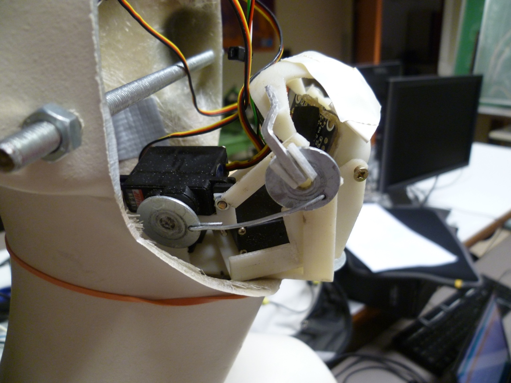
The modifications of the prototype eye module can be seen on the pictures below:
Problem 2
Another problem was the material used. For the thickness used, it was not stiff enough. When a motor tried to exert
a couple, due to the size difference in the transmission and the friction, the motor was rather pulling than turning the axis. This was the reason we broke or
replace some parts. The axis for the horizontal, as well as for the vertical rotation of the eye-ball, has been replaced by screws with nuts and washers glued
or soldered together.
Another reason for breaking parts was the thin therefore weak design because of the material used. This was necessary because everything had to be small enough to fit inside the head of the mannequin and because we wanted the eye-ball to be close to the face to keep everything as natural as possible, which limited our movements.
This weakness caused a real slowdown of the project. A lot of plastic parts had to be replaced by metallic equivalents (washers, screws, bolts) that had to be glued on existing plastic parts. Additionally, other plastic parts also had to be glued on the resulting structure to make it more stiff. In the end, this composite assembly made of plastic, glue and metallic parts worked but was very fragile and not reliable.
Solution 2
The use of machined aluminum or another material rigid enough instead of the plastic of the 3D printer would have led to far better results and would have saved a lot of time.
Limitations and possible future improvements
The main limitation for speed, reactivity and accuracy is currently due to two reasons.
First of all, the image quality (not the definition) of the webcam. A perfect focus was difficult to achieve and the image presented too high contrasts, which was expectable for this cheap webcam. A device with better optics, better image sensor and image treatment and mainly higher frame rate would led to a better detection of faces in all conditions.
The second limitation is the algorithm used, or the classifier file used that could not be optimized for fast detection. Though the openCV algorithm has some performance tweak options, the use of a better, more performance-oriented algorithm such as those found in digital cameras could provide better results. In fact, the main issue was that because the webcam was embedded in the eye, the resulting image was moving with each motion of the eye. If the amplitude of the movement is too large, the detected face in the image changes position too fast for the algorithm to keep track of it. This problem was overcome by incrementing the position of the servos slowly enough. This is because the main weakness of the openCV algorithm is that it is very slow to detect the first face. Once the face is detected and if it moves slowly enough, the frame rate is quite high, but once the face is lost, the frame rate drops dramatically because it looks deeply in the image to find a face.
To summarize, here are the two points to improve:
- Better webcam with higher frame rate and better image quality
- Use of an algorithm fast enough to detect a face for the first time. A lead to follow is the use of LBP features instead of Haar-like features
On this topic, the following document is worth reading http://cs229.stanford.edu/proj2008/Jo-FaceDetectionUsingLBPfeatures.pdf
Note that a lbp-based classifier was tried out during the development of the software for this project (the included lbpcascade_frontalface.xml file), but it did not allow an option such as CV_HAAR_FIND_BIGGEST_OBJECT (i.e. it was detecting multiple faces) thus, it was slower than the haar-based classifier (haarcascade_frontalface_alt.xml) which was sped up a lot by the use of this option.
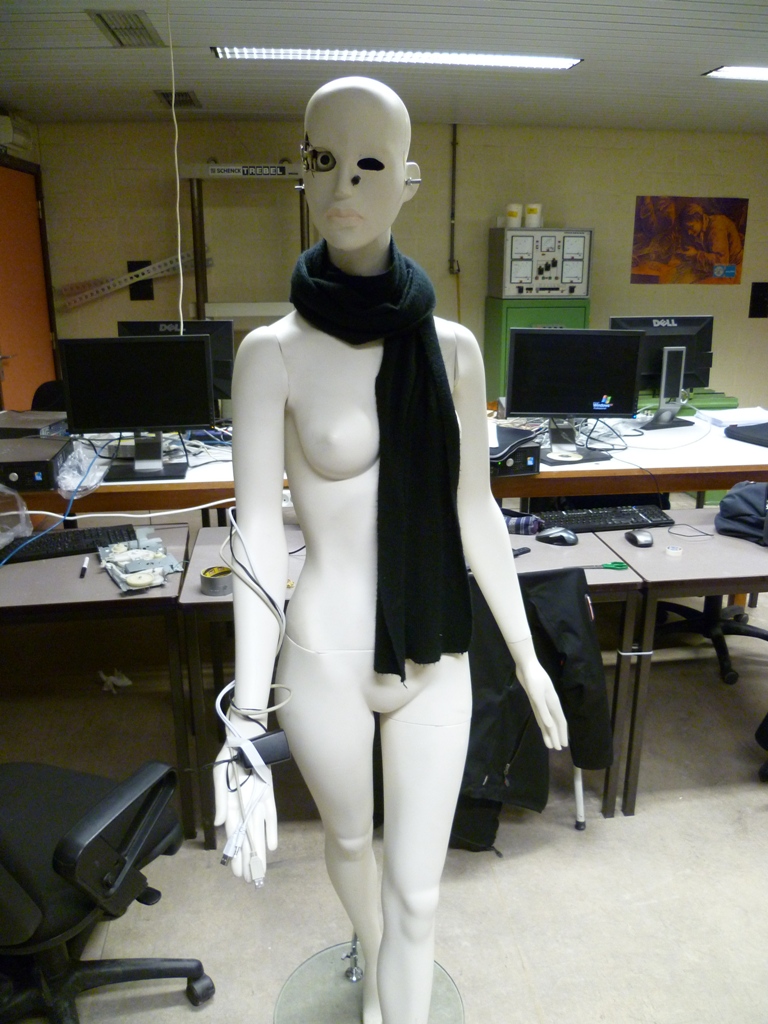
Pictures
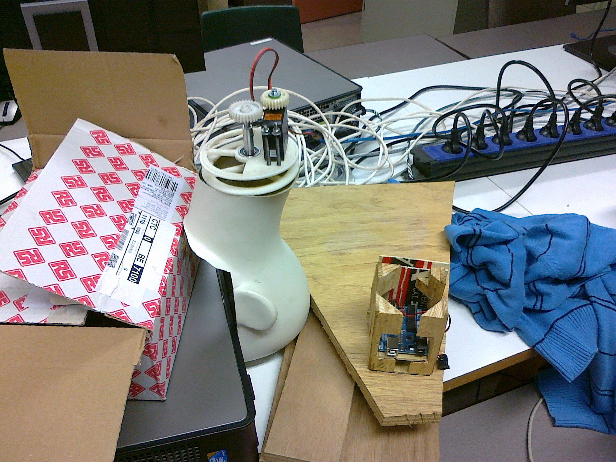
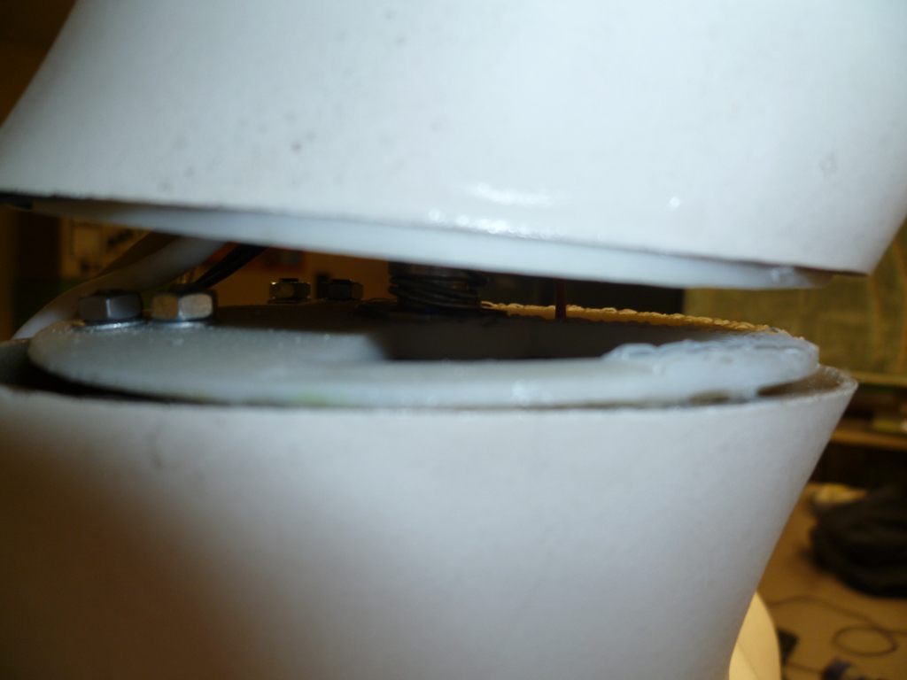
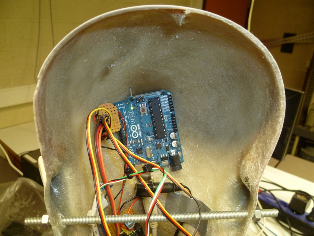
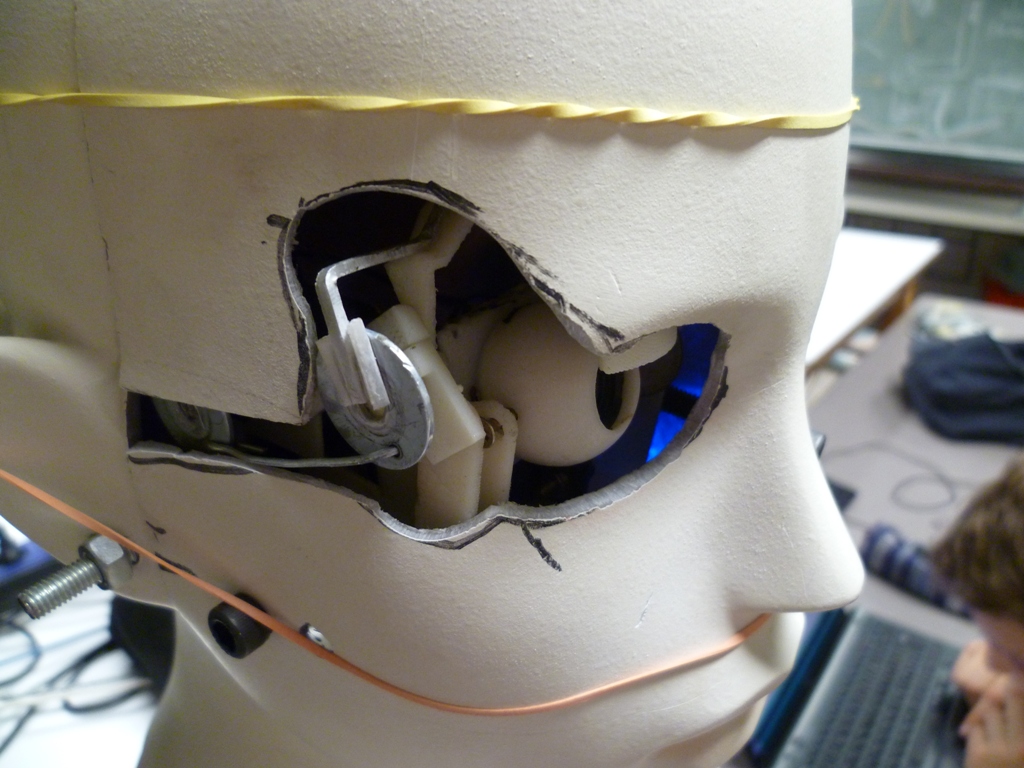
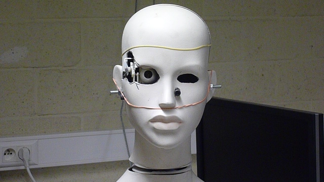
The pictures below show different stages of the completion : the mechanism for the neck, the fixation of the Arduino board at the bottom of the head, the fixation of the eye inside the head, the unexpected cutting of the face and the final result.
Videos
The following video shows a test of the program implemented into the arduino board. It is not a programmed sequence of movements but real-time computed movements resulting from the face detection of a member of the group who was moving behind (you can see a glimpse of the webcam view on the computer's screen on the background). However the test was made in open loop i.e. with the webcam of the laptop and not the one embedded in the eye.
This video shows the disassembly of the face.
This video shows a test of face detection in closed loop (via the embedded webcam) after completion of the assembly.
Final result after optimisation of the algorithm (more reactive and smoother movements).