The construction consists of 4 parts:
-
A bridge over the strings, placed where u would normally strike the strings with a plectrum. This will position the following part.
-
A device to strike the string with a plectrum.
-
A construction that slides over the strings, using a roll to press the strings.
-
A device mounted above the roll that presses the roll tightly against the strings
Each of the previous
parts is steered by one stepper motor. A more
detailed discussion follows now.
The motors
2 Of the used motors are
identical. All of the motors are stepper motors. Controlling a stepper motor
is not that easy compared to a DC motor. The advantage is that we can really
control how many steps a motor makes. This is especially necessary in each
of the parts.
It's very obvious that it's impossible to start a motor immediately at high
speed. Therefore it's necessary to start at a low speed and accelerate to a
maximum speed. We can't accelerate infinitely. The motor would lose it's
torque. Since P = C . w
;where P = power, C = torque, w=
pulsation .
Therefore we must stop the acceleration at a certain speed. This speed is
different for each motor since they're all different and have to carry
different loads.
When a motor has to exercise force it needs much power. When it is in rest
it shouldn't use as much power. Else it would heat up too much and cause to
damage itself. The power applied however shouldn't be zero since then the
motor would lose all of its torque and we wouldn't be sure which step the
motor is at. Maybe the motor has rotated without our wanting it to. To avoid
this we designed an electronic circuit that
allows us to apply 2 different currents to each motor. With the
microcontroller we can then tell each motor when it has to use high power
and when low power.
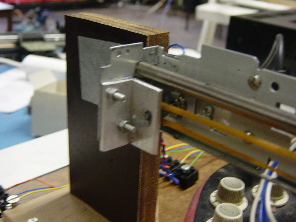
The bridge is made from
an old HP printer. It was completely disassembled and placed horizontally
above the strings on 2 wooden standards.
This is something that was available from the previous time. One big problem
came alive though. The motor used in this part was a unipolar stepper motor
BUT the electronic circuit we designed was for bipolar stepper motors.
Sometimes it is possible to control a unipolar motor in a bipolar way, but
this is only possible if the unipolar motor has 6 wires. In this case we had
bad luck since there were 5 wires. So we had to replace the motor with a
bipolar motor.
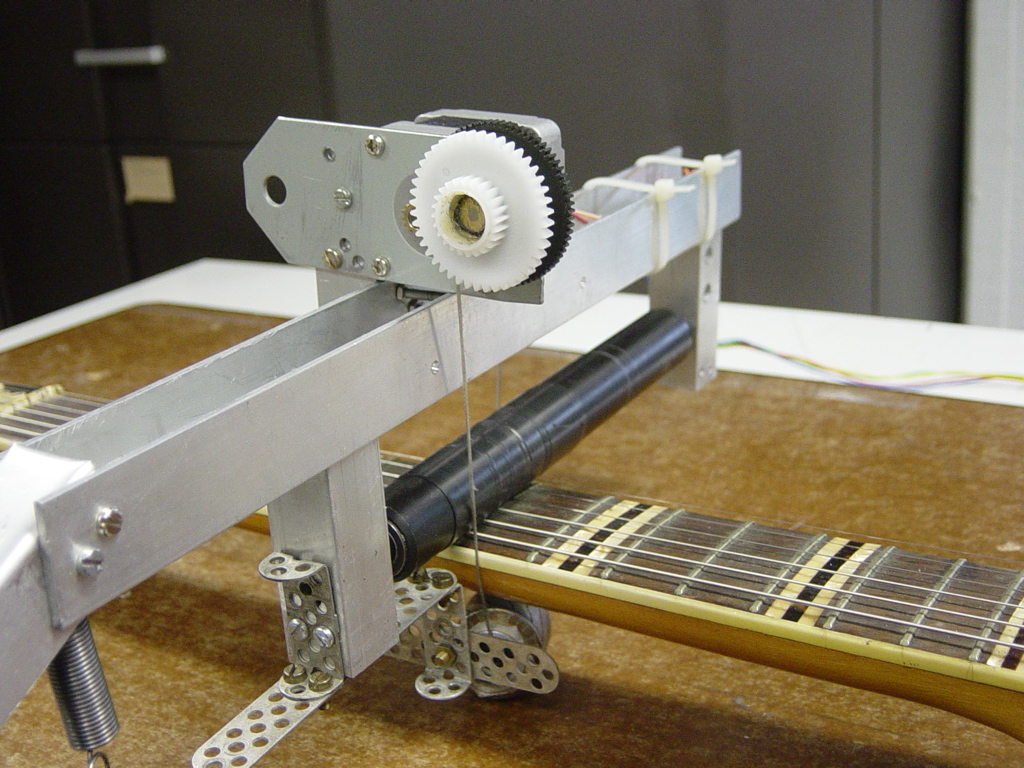
There was a little gear on the unipolar motor we had to recuperate and fix
on the unipolar motor. We used an ingenious system for this. Following
picture demonstrates how.
The gear on the motor itself is pressed into a relatively thick plastic disc. This makes the disc rotate. On the other side of the disc the axis with the little desired gear is mounted. The problem with this construction was that the little axis wasn't completely collinear with the axis from the motor. This causes the problem that the moving part moves in shocks. Besides this negative effect, the motor is too weak to overcome the higher loads. Fixing the other end of the little axis with a bearing on the bridge solved this problem. This is shown in following picture.
This way the motor runs smoothly.
To initialize the position of the moving part on the bridge, a microswitch
is fixed on one end of the bridge.
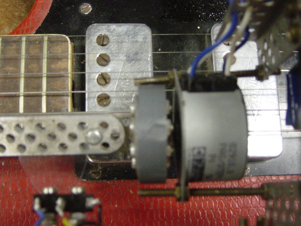
The final result of the bridge can be admired here:
Moving along the bridge
is a device to rotate a plectrum to strike the string it's above. This is a
whole new concept. The previous time there was only a plectrum fixed on the
bridge that moved horizontally and thus striking the (only 2) strings. With
this concept it's possible to skip strings you don't want to strike and
specifically strike the desired string.
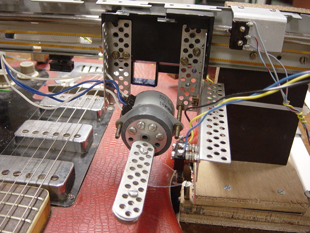
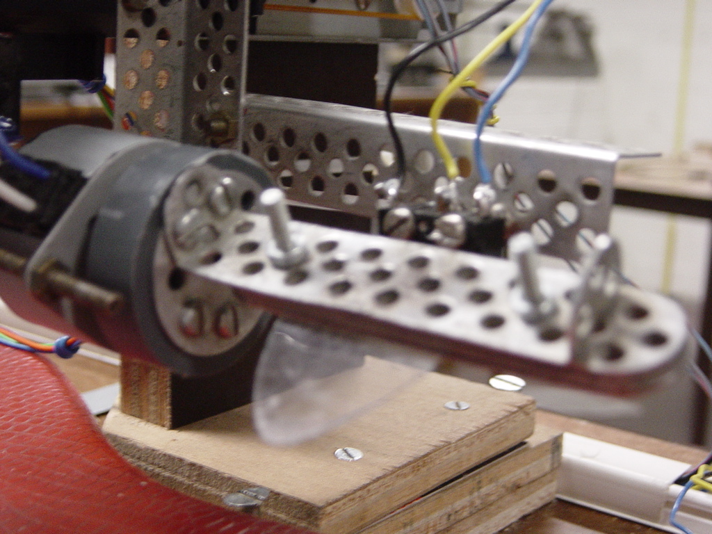
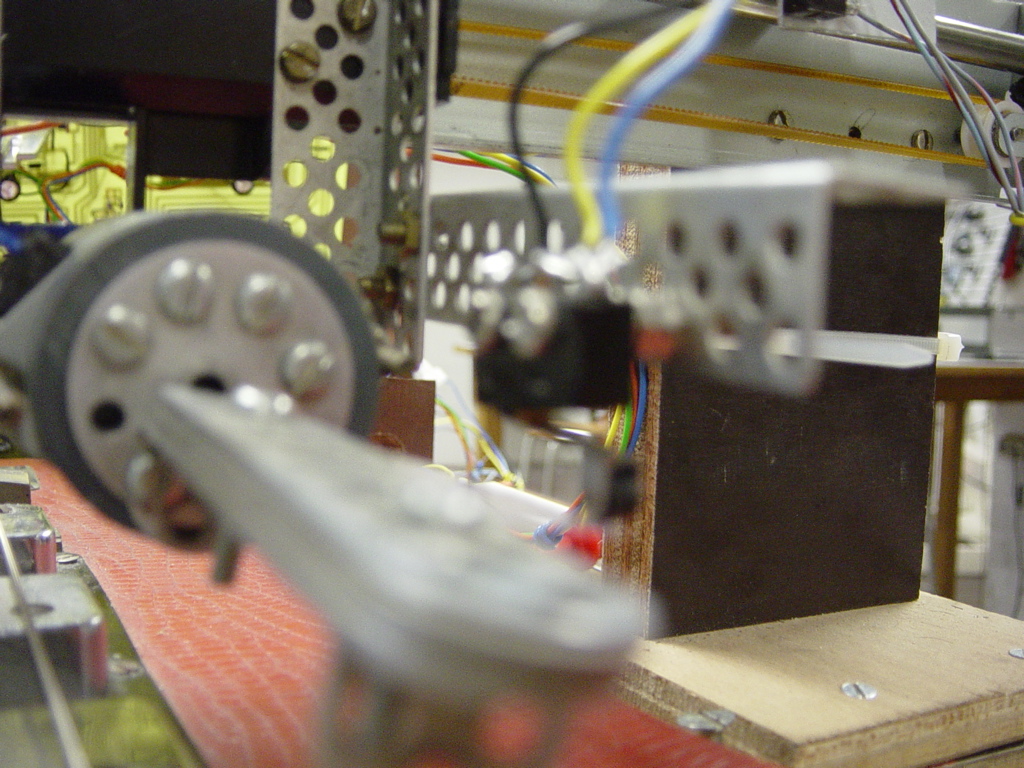
The challenge here was
1. to fix a bipolar stepper motor onto the moving part of the
bridge
2. to fix a plectrum on the motor
3. to fix a microswitch next to the plectrum so that the
plectrum can press the switch.
.
For each of these challenges we used mecano - a handy set of metal pieces in
all kind of forms with holes in that make it possible to screw the pieces
together, thus making a construction.
Challenge 1
After screwing mecano pieces onto the moving part, it was easy to mount the
stepper motor with bolts and nuts on those pieces. Because of the many holes
in the mecano it's easy to adjust the height of the motor.
Challenge 2
Once the motor is fixed the problem of fixing the plectrum on the axis of
the motor arises. There was a little gear available on the axis which could
not be removed. Thus the same proposition as before was made. Namely to use
a plastic disc again. The disc was pressed and then glued into the gear. On
the other side of the disc another mecano construction was made in which we
could stick a plectrum. It's really handy because the plectrum could be
adjusted in height by loosening some bolts, moving the plectrum and
refastening the bolts. We are very proud of this concept.
Challenge 3
Placing the microswitch at the right position didn't require a lot of
thinking. Again a plate of mecano was used to fix the switch at its rightful
place.
Following pictures visualize the previous words.
This is a part where we
encountered lots of problems and frustrations. We started with a
construction from the previous project. Just like the bridge it was made
from an old printer. This construction had to be modified greatly.
The moving part on the printer-slider is a little car that moves in 2 rails.
On the rail was an arm with a roll that pressed on the strings through a
spring which was pulled between the arm and the little car.
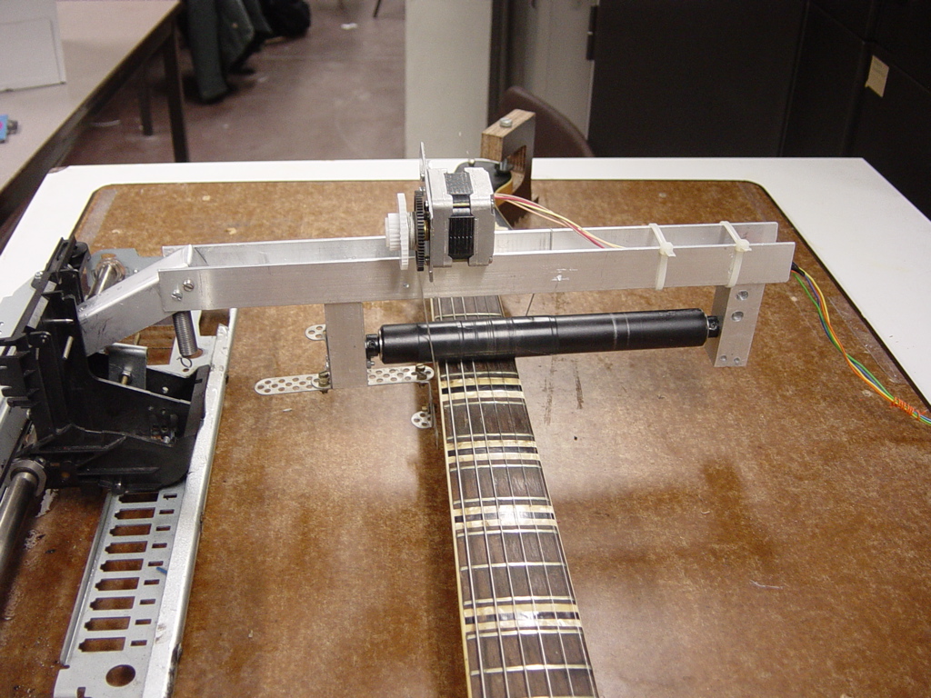
Now we use 6 strings instead of 2 from the previous project, so the arm and
roll had to be completely remade. The search for a suitable roll that wasn't
too big and yet long enough, took a while but we had success nevertheless.
It took us a lot of sawing and drilling to fabricate the arm out of aluminum
U-profiles. The roll itself was fixed between 2 solid aluminum beams. In
these beams it was necessary to thread so that we connect the beams to the
bottom of the arm (U-profile) with bolts. So a lot of learning to work with
these mechanical tools happened as well during the making of this part.
The motor used for this part was a unipolar motor unfortunately. But
thankfully it was a stepper motor with 6 wires. This means it could be
controlled in a bipolar way. And that's exactly how we control this motor.
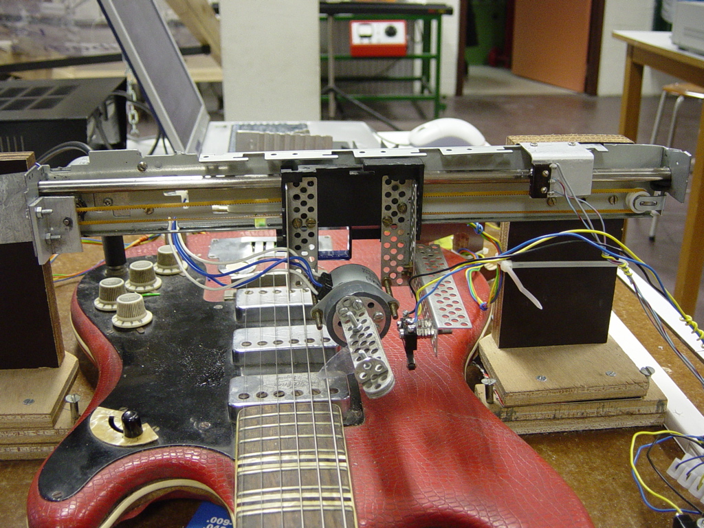
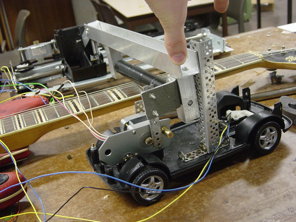
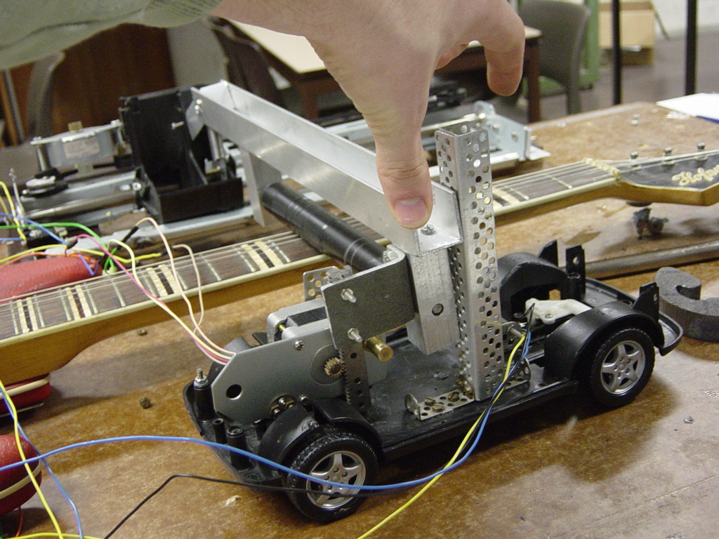
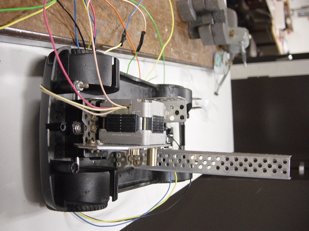
One of our ideas which appeared later to be a malfunctioning idea was to
make another little car roll parallel with the little car on the arm. The
car would have another stepper motor aboard that could make the arm lift up
with a gear rack attached to the arm which is lifted by the gear on the
motor aboard the little car. The result is shown in following pictures. Also
the crafted arm with the roll is visible.
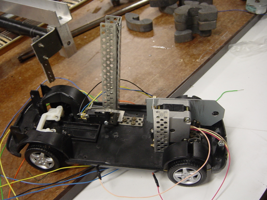
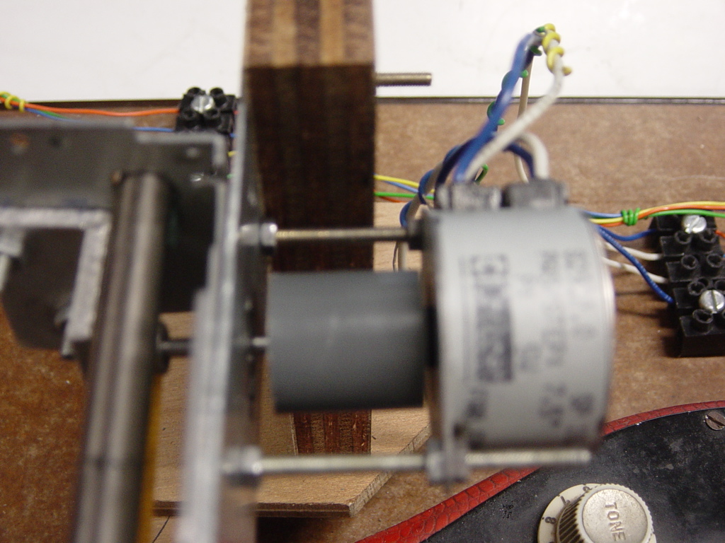
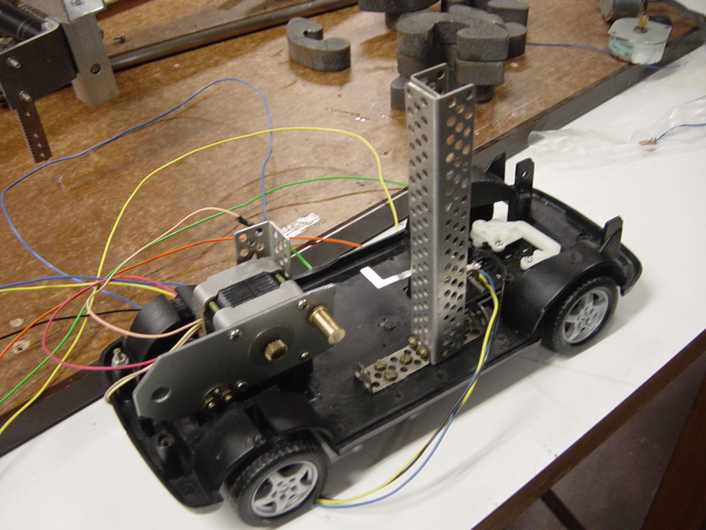
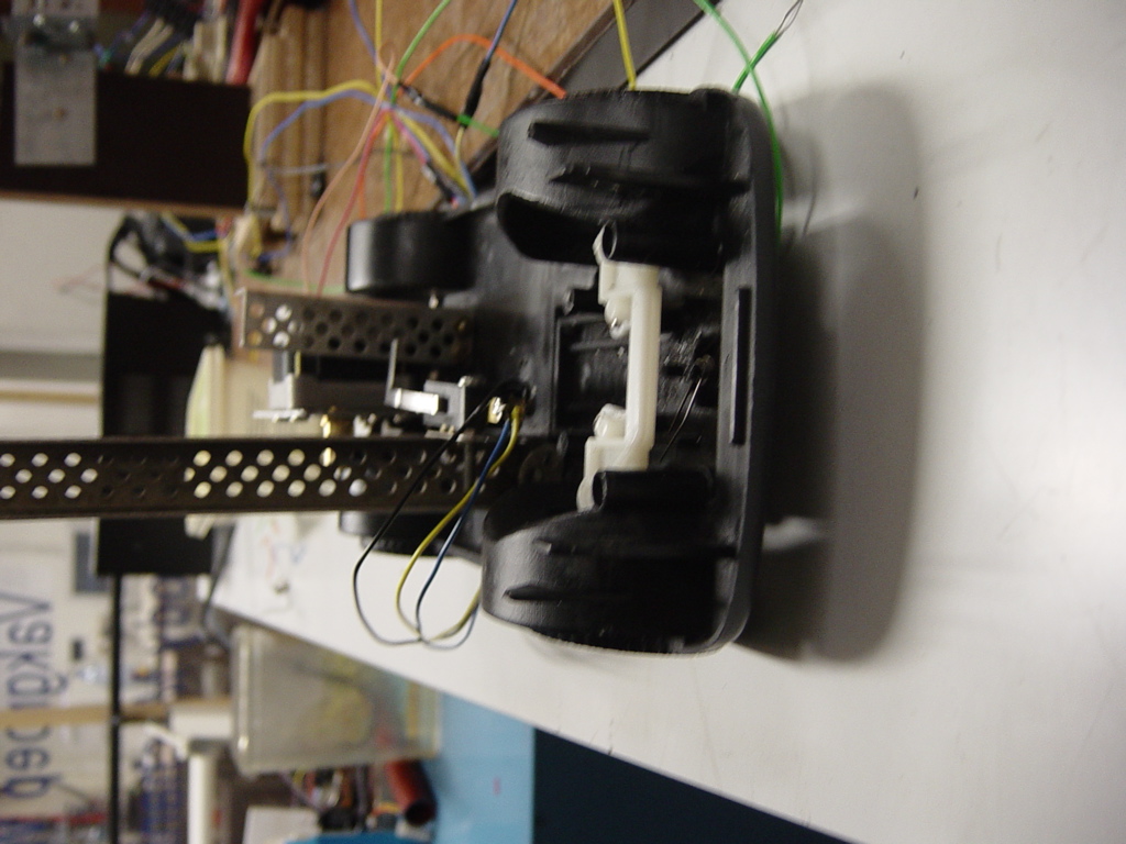
The making of the car took us a lot of time too. An old toy car was found in
the cupboard. We completely tuned the toy car. It's really looking
impressive with a big stepper motor aboard. The front wheels were not
allowed to rotate since the toy car had to move parallel with the
printer-slider. This wasn't an easy task but we managed with some drilling,
scraping and screwing bolts.
Fixing the motor on the car wasn't an easy job either. We used mecano again
since it's such a handy tool. To make sure the car would always be in
contact with the arm, a long pole was made out of mecano (again :) )and
placed vertically on the toy car. In the following pictures our toy car can
be admired from different angles.
This construction seemed useful until we discovered that the stepper motor
that moved the roll was not powerful enough to overcome the resistance of
moving the little car over the rails in the printer-slider. On the little
car there was a little wheel which was pulled up by the spring attached
between the car and the arm (used to pull the arm down). We noticed that if
this wheel wasn't pulled up, the stepper motor could deliver enough power to
at least move the car. There were 2 options now: change the stepper motor
with another more powerful one, or think of another concept where the spring
wasn't needed.
But since no other strong enough stepper motor was available we had to go to
the next option. So we came to concept number 2. This brings us to the next
part where this will be explained more deeply.
Top
Back
The pressing mechanism
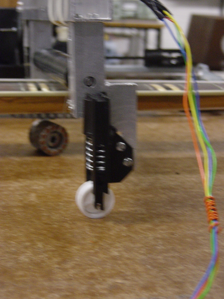
This 2nd concept was attaching a roller on a spring at the end of arm to push the arm upwards this time. The spring between the arm and the car on the printer-slider was removed. It looks like this:
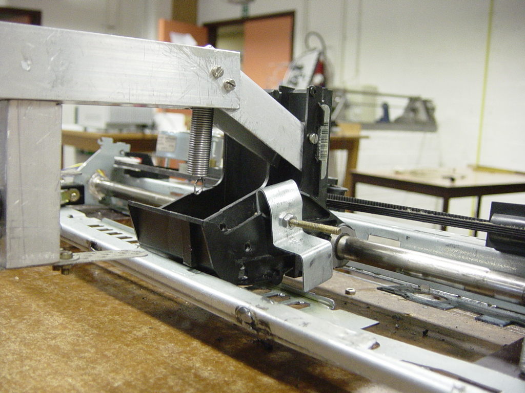
Then the motor on the toy car was removed and placed on top of the arm and
it would now pull the arm down by means of a little rope going under the
guitar. With this solution the stepper motor on the printer-slider could now
move freely.
Around the rope a weight was added so that the rope would always move down
and not stay behind and thus block the movement of the roller.
With this mechanism the roll could move down and up. It allowed us to make
sure the roll wouldn't slide over the strings when the roll was moved
because this would cause the "sliding sound" which was undesired.
But apparently the motor of this part wasn't strong enough to pull the arm
down on the guitar against the force of the spring from the roller. Because
of this we had to remove the roller and live with the "sliding effect".
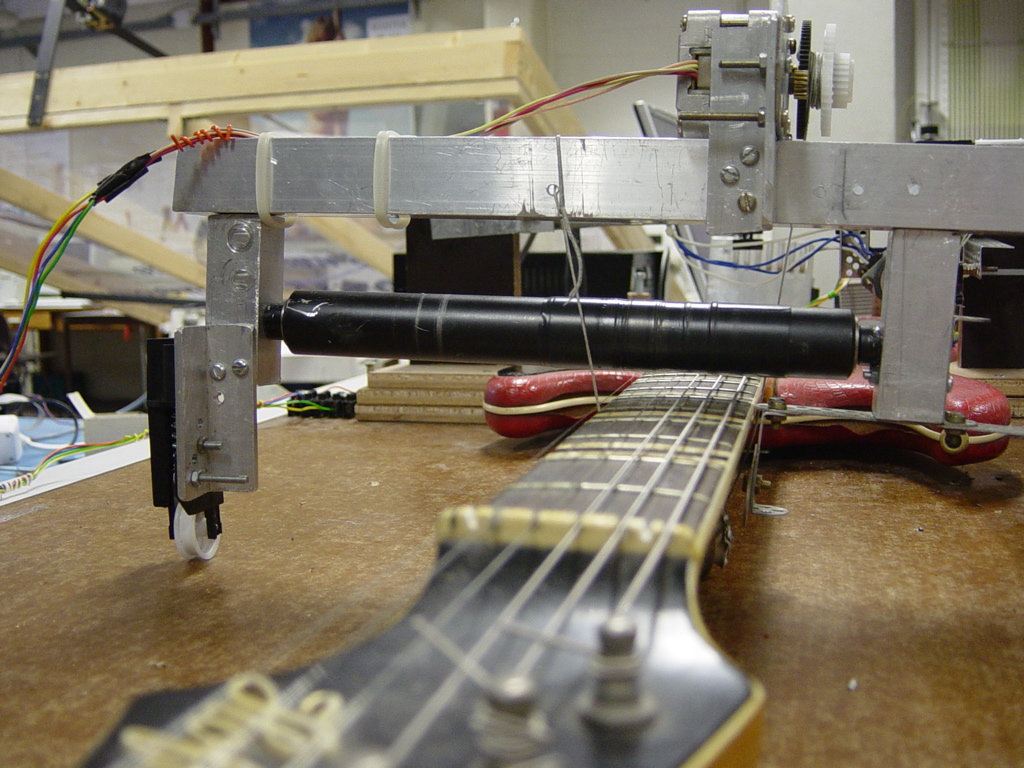
The stepper motor used in this part is a bipolar stepper motor, taken from a
scanner. It's a motor of our own. It's also the strongest motor. This is
necessary for this part to make sure the roll is pressed tightly against the
strings.
This nice concept can be admired in following photographs: