Programming
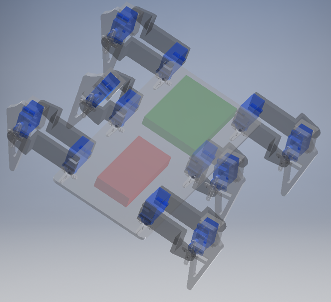
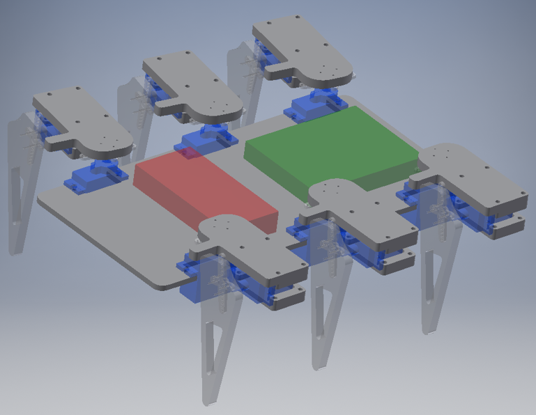
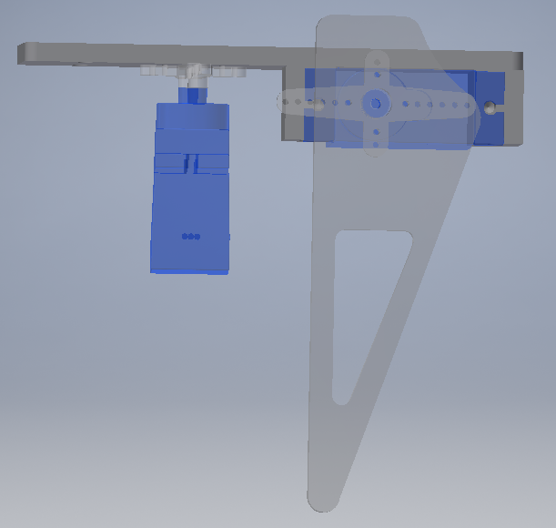
Before we start programming, we must understand how our robot will move. The hexapod will have 6 legs and these will be paired three by three, creating two groups. Looking at the following figure, this statement is better understood:
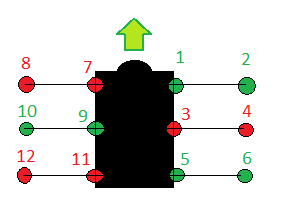
We decided to apply the following sequence to determine the movement of our hexapod:
- Motor 2, 10 and 6 go up
- Motot 1, 9 and 5 rotate forward
- Motor 2, 10 and 6 go down
- Motor 4, 8 and 12 go up
- Motor 1, 9 and 5 rotate back
- Motor 3, 7 and 11 rotate forward
- Motor 4, 8 and 12 go down
- Motor 2, 10 and 6 go up
- Motor 3, 7 and 11 rotate back
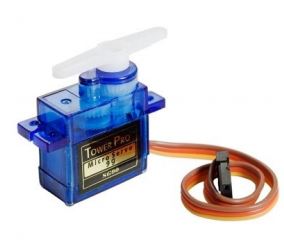
Defined the movement, we had to face the calibration of the servos. Calibrating means finding the ranges of positions in which we want our motors move in.
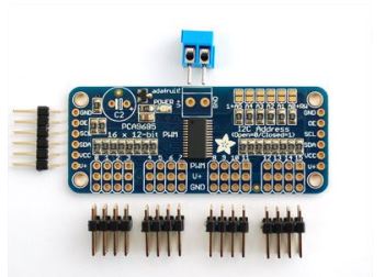
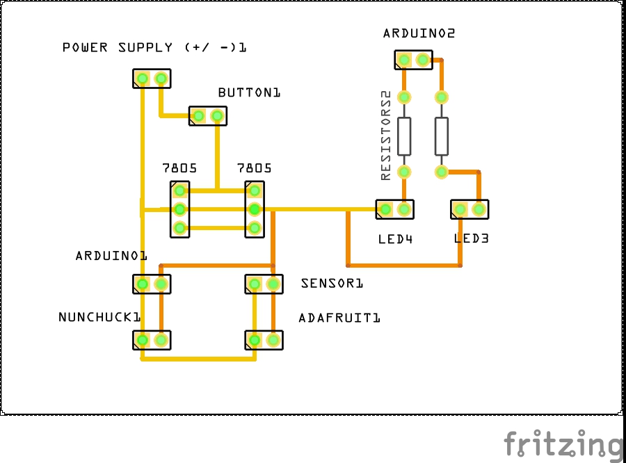
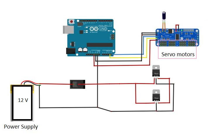
Once the servos were calibrated, we proceeded to download the Adafruit and Nunchuck libraries to control the 12 motors at once through the Wii joystick.
Inside the nunchuck library, we had to look at the ranges for which we took values forward and backward to be able to perform functions.
Having all this clear, we proceeded to the programming. We have done a very simple programming, sequential and with functions that have allowed us to handle the hexapod as we wanted.
In the following code, we are going to talk about the function “go forward”. To see all the code, please download the “.ino” file.
We started by defining the libraries and the adafruit:
#include <Servo.h>
13 MECHATRONIC PROJECT: HEXAPOD
#include <Wire.h>
#include <Adafruit_PWMServoDriver.h>
Adafruit_PWMServoDriver servos = Adafruit_PWMServoDriver(0x40);
WiiChuck chuck = WiiChuck();
After that, we have defined a vector which contains all the servo positions (values obtained by the calibration). As it is shown Fwd = mueve shoulder forward, Bwd = mueve shoulder backward , Hor = pon las legs horizontal and Ver = pon las legs vertical.
unsigned int FWD[] = {0, 190, 0, 185, 0, 200, 0, 160, 0, 130, 0, 110, 0};
unsigned int REST[] = {0, 160, 0, 150, 0, 170, 0, 185, 0, 155, 0, 135, 0};
unsigned int BWD[] = {0, 120, 0, 120, 0, 140, 0, 230, 0, 190, 0, 165, 0};
unsigned int HOR[] = {0, 0, 120, 0, 170, 0, 300, 0, 300, 0, 340, 0, 120};
unsigned int VER[] = {0, 0, 290, 0, 350, 0, 130, 0, 130, 0, 135, 0, 290};
Following, we have defined the variables that we are going to use:
int i=1;
int moving = 4;
int NOgo = 5;
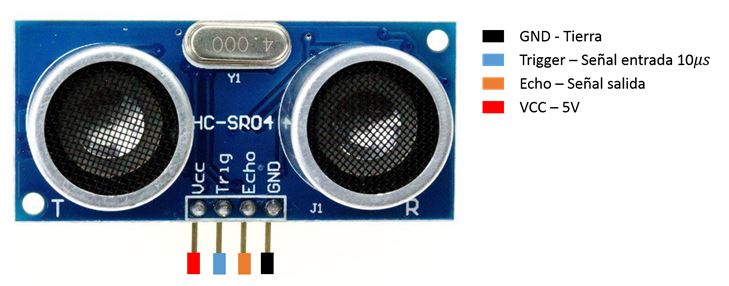
#define echoPin 3
#define trigPin 2
long duration, distance;
We define the setup where we initialize all the variables:
void setup() {
Serial.begin (9600);
pinMode(trigPin, OUTPUT);
pinMode(echoPin, INPUT);
pinMode(moving, OUTPUT);
pinMode(NOgo, OUTPUT);
chuck.begin();
chuck.update();
servos.begin();
servos.setPWMFreq(60);
We define the function “go forward”:
void GOFWD(){
digitalWrite(moving, HIGH);
Serial.println("He entrado en GOFWD");
servos.setPWM(2,0,HOR[2]);
servos.setPWM(6,0,HOR[6]);
servos.setPWM(10,0,HOR[10]);
Serial.println("Arriba 2 6 10");
delay(250);
servos.setPWM(1,0,FWD[1]);
servos.setPWM(5,0,FWD[5]);
servos.setPWM(9,0,FWD[9]);
Serial.println("Delante 1 5 9");
delay(250);
servos.setPWM(2,0,VER[2]);
servos.setPWM(6,0,VER[6]);
servos.setPWM(10,0,VER[10]);
Serial.println("Baja 2 6 10");
delay(250);
servos.setPWM(4,0,HOR[4]);
servos.setPWM(8,0,HOR[8]);
servos.setPWM(12,0,HOR[12]);
Serial.println("Arriba 4 8 12");
delay(250);
servos.setPWM(1,0,REST[1]);
servos.setPWM(5,0,REST[5]);
servos.setPWM(9,0,REST[9]);
Serial.println("Atras 1 5 9");
delay(250);
servos.setPWM(3,0,FWD[3]);
servos.setPWM(7,0,FWD[7]);
servos.setPWM(11,0,FWD[11]);
Serial.println("Delante 3 7 11");
delay(250);
servos.setPWM(4,0,VER[4]);
servos.setPWM(8,0,VER[8]);
servos.setPWM(12,0,VER[12]);
Serial.println("Abajo 4 8 12");
delay(250);
servos.setPWM(2,0,HOR[2]);
servos.setPWM(6,0,HOR[6]);
servos.setPWM(10,0,HOR[10]);
Serial.println("Arriba 2 6 10");
13 MECHATRONIC PROJECT: HEXAPOD
delay(250);
servos.setPWM(3,0,REST[3]);
servos.setPWM(7,0,REST[7]);
servos.setPWM(11,0,REST[11]);
Serial.println("Atras 3 7 11");
delay(250);
digitalWrite(moving, LOW);
Serial.println("He salido de GOFWD");}
And also here is the programme for the sensor
void SENSOR(){
digitalWrite(trigPin, LOW);
delayMicroseconds(5);
digitalWrite(trigPin, HIGH);
delayMicroseconds(5);
digitalWrite(trigPin, LOW);
duration = pulseIn(echoPin, HIGH);
distance = duration/58.2;
Serial.print("Distance:");
Serial.println(distance);
delay(250);}
And the programm for the nunchuck
void JOYSTICK (){
delay(20);
chuck.update();
Serial.print(chuck.readJoyX());
Serial.print(", ");
Serial.print(chuck.readJoyY());
Serial.print(", ");
Serial.println();}
We define the void loop (the function that is going to repit). Here we have called all the other functions created:
void loop(){
SENSOR();
JOYSTICK();
if(distance>20){
if((chuck.readJoyY() > 100)&&(chuck.readJoyX() >
100)){
RESET();}
else if((chuck.readJoyY() > 100)&&(chuck.readJoyX() < -80)){
//nunchuck in topleft corner
RESET(); }
else if ((chuck.readJoyY() < -100)&&(chuck.readJoyX() < -100)){
//nunchuck in bottomleft corner
RESET(); }
else if ((chuck.readJoyY() < -100)&&(chuck.readJoyX() > 100)){
//nunchuck in bottomright corner
RESET();}
else if ((chuck.readJoyY() > 122)){
GOFWD(); }
else if(chuck.readJoyY() < -131){
GOBWD();}
else if ((chuck.readJoyX() < -122)){
GOLFT();}
else if ((chuck.readJoyX() > 129)){
GORHT(); }
}
if(distance<20) //CAN'T MOVE
{
RESET();
digitalWrite(NOgo, HIGH);
delay(250);
digitalWrite(NOgo, LOW);
delay(250);
digitalWrite(NOgo, HIGH);
delay(250);
digitalWrite(NOgo, LOW);
delay(250);
digitalWrite(NOgo, HIGH);
delay(250);
digitalWrite(NOgo, LOW); }
Serial.println("CicloTerminado");
Serial.println(i);
i++;
}

.png)
.png)
.png)
.png)
.png)
.png)
.png)
.png)