Presentation
- The robot is an automatically driven supermarket trolley that is able to follow a target customer in a store. This technology would lead to comfort improvement since customers wouldn't need to carry a heavy bag, allowing them to walk freely. The robot is even more useful for disabled and old people with reduced physical abilities. The robot stays behind the customer at a short distance such that he/she is able to put articles in the trolley standing by. The automated trolley should then be able to detect the relative position of the target customer in order to follow him and maintain a safe distance. Also the robot should be able to detect any obstacle to avoid any kind of collision with an object, a human or another robot to insure safety. Finally if there is a quick possibility to go around an obstacle to reach the customer, the robot should be able to find the path to do so.
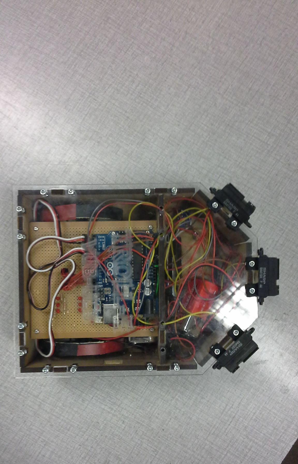
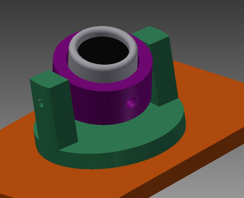
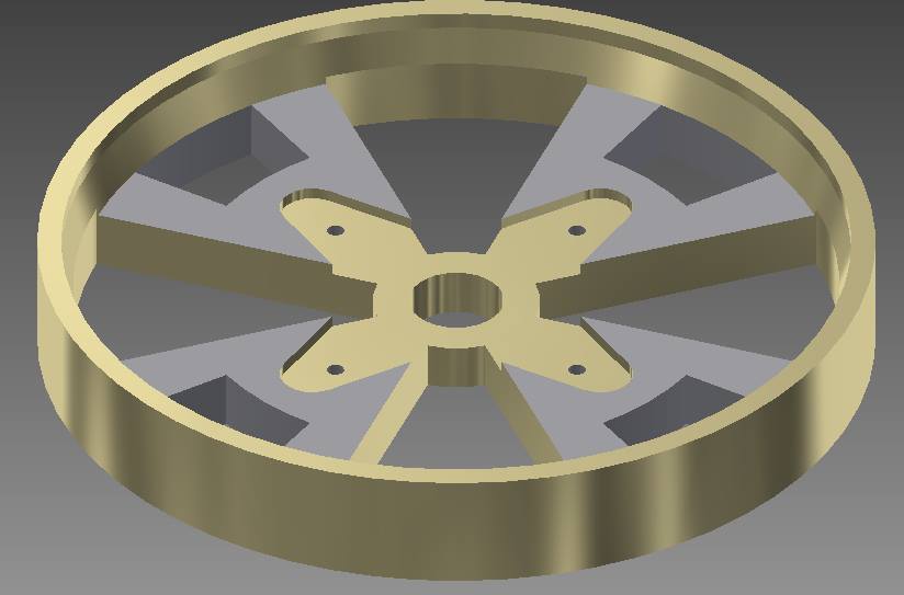
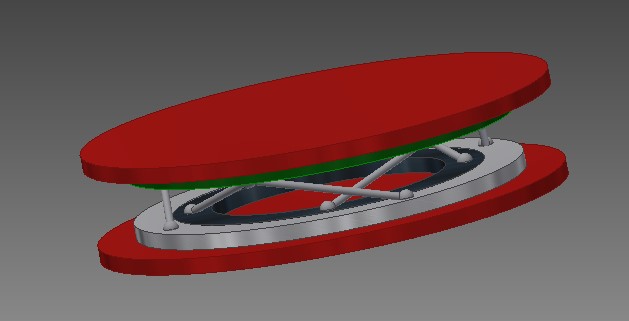
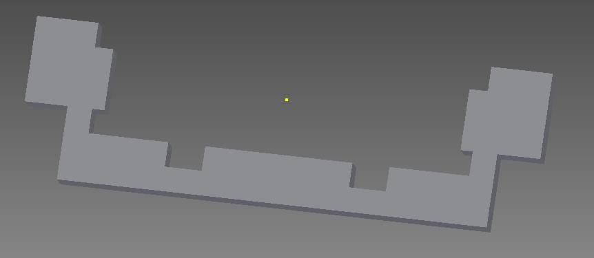
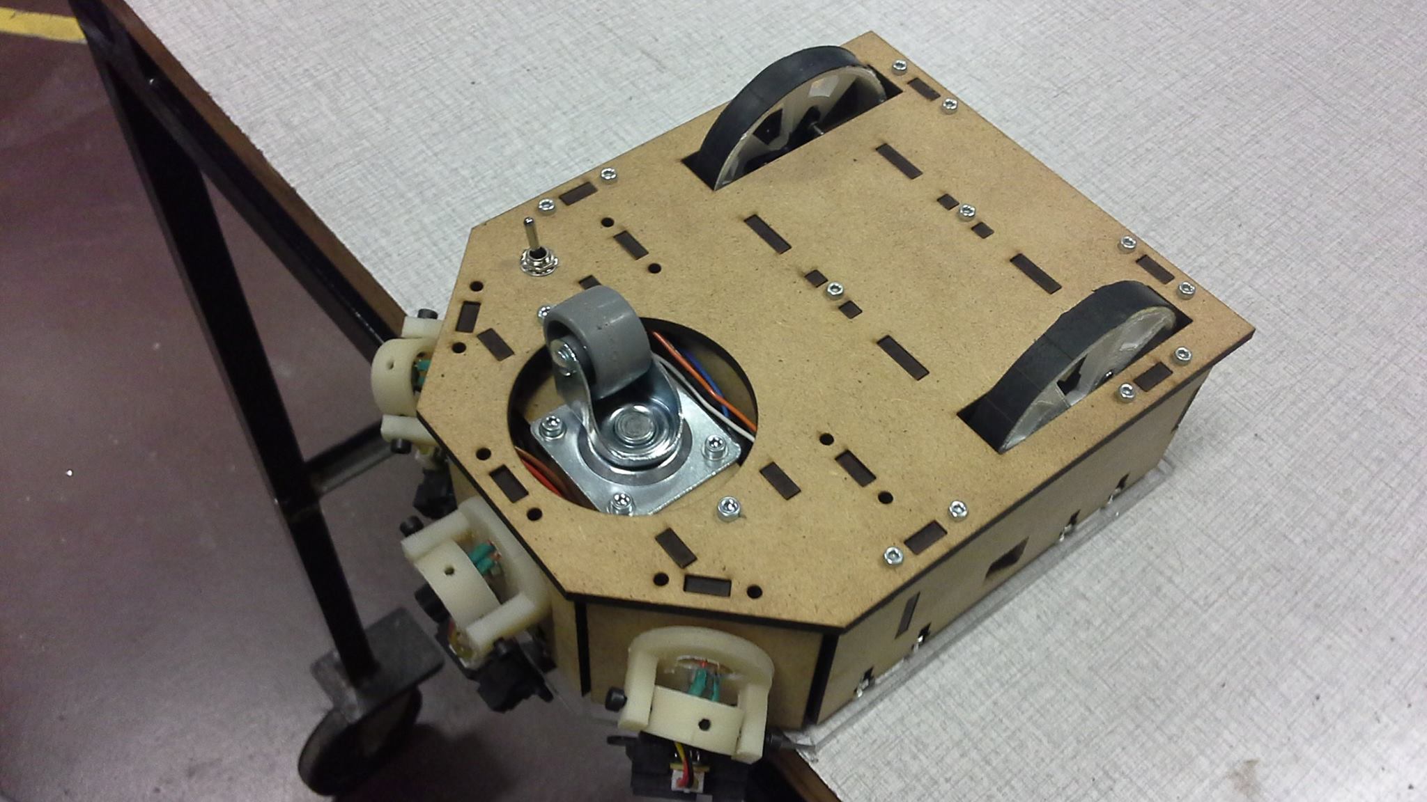
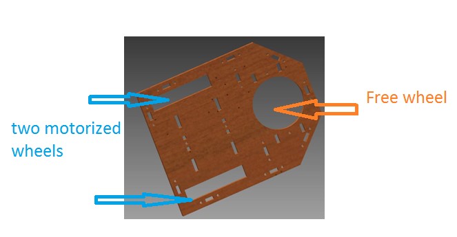
- One free wheel in front (free in direction) and two motorized wheels on the back are used so that the robot is able to change its speed and direction (using the two motorized wheels).
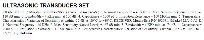
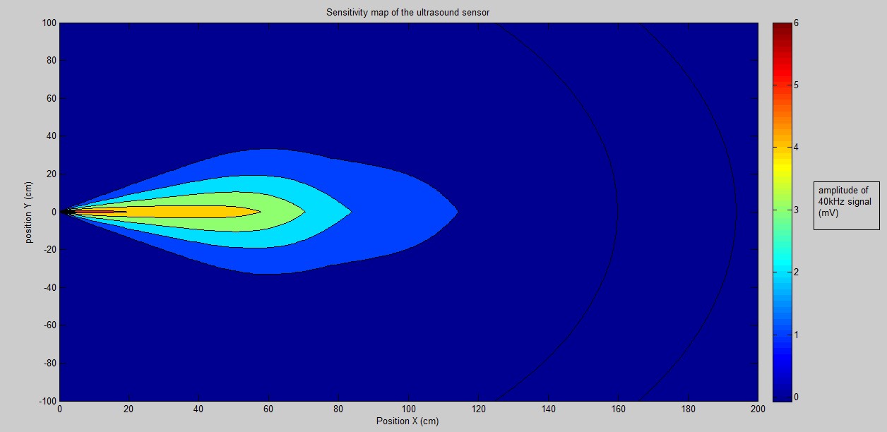
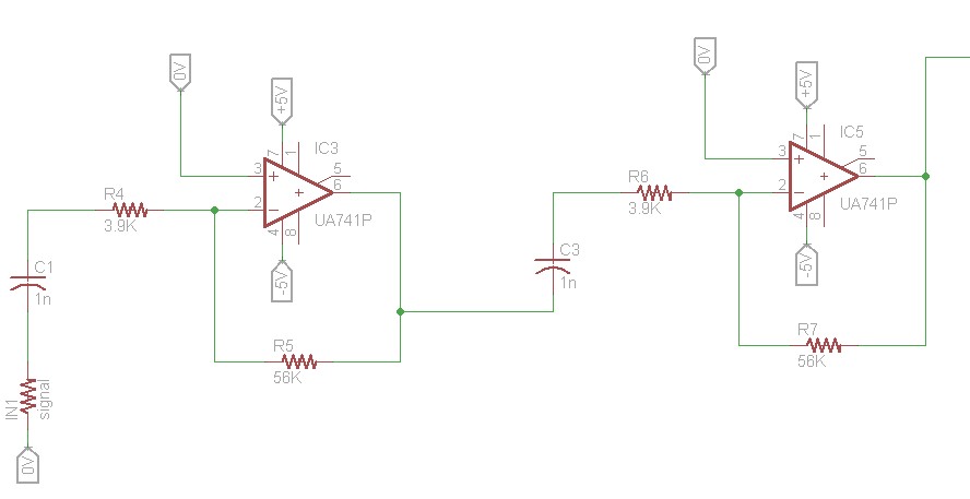
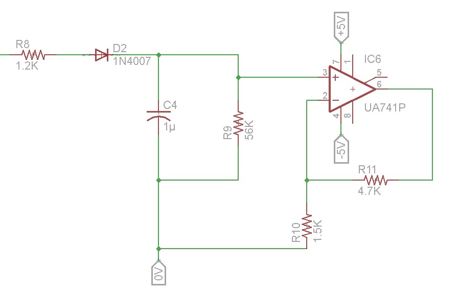
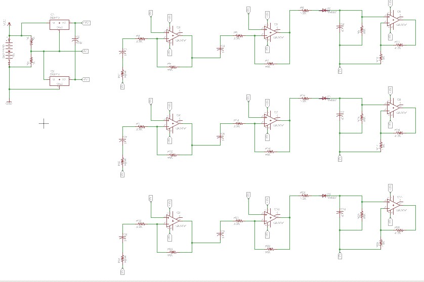
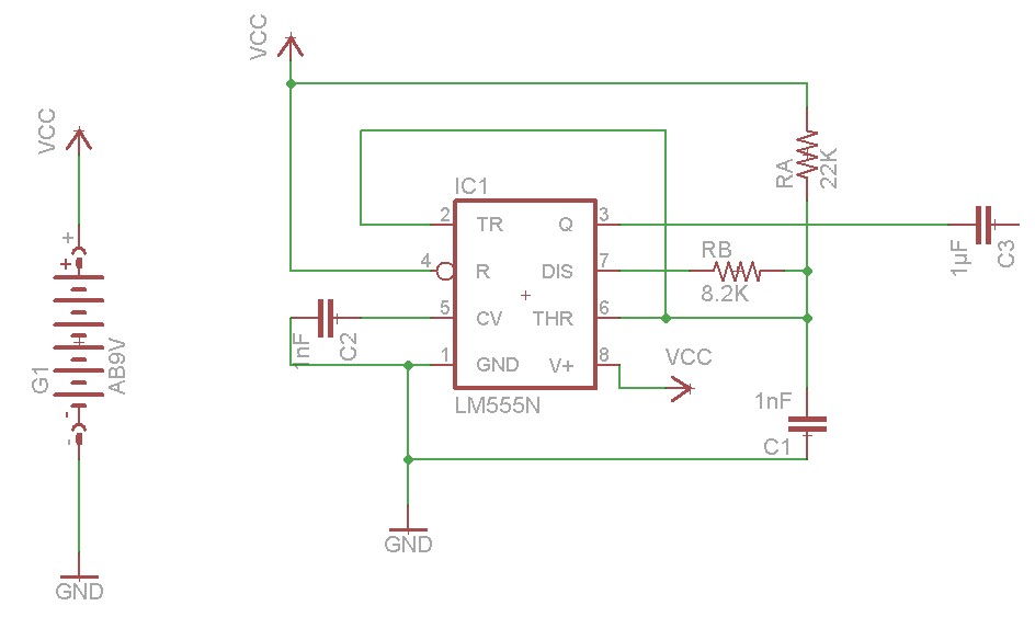
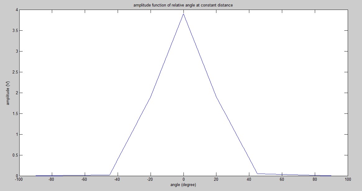
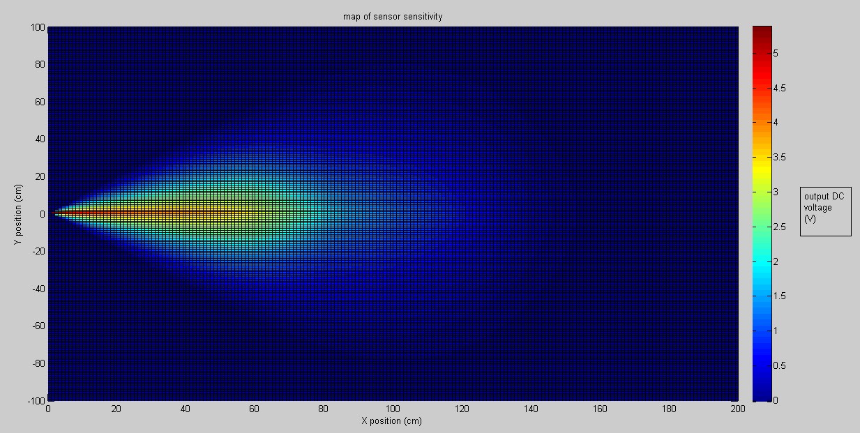
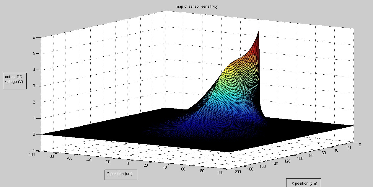
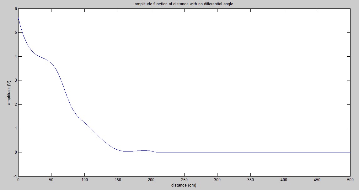
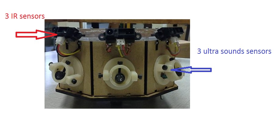
- Three ultrasound sensors are used as customer detectors, so that the robot will be able to find his target customer which will carry a little ultrasound emitter. The three sensors will be oriented in different directions so that the difference of amplitude will be used to find the direction towards the target, while the average amplitude will be used to determine the distance.
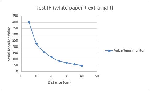
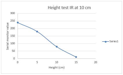
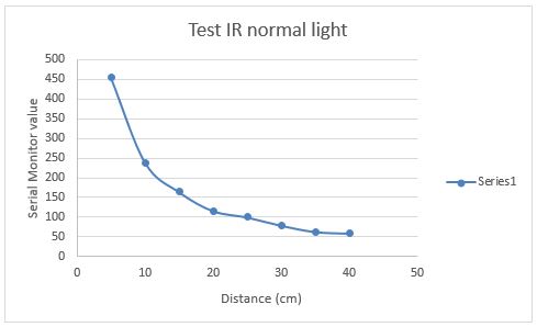
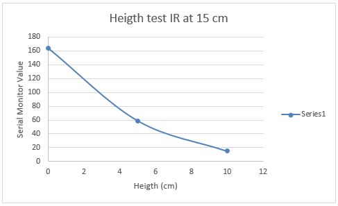
- Three Infrared detectors with different angle are used in order to detect obstacles. If the measured value of one of the IR sensors exceeds a threshold, an alternative path is provided or complete standstill is obliged.
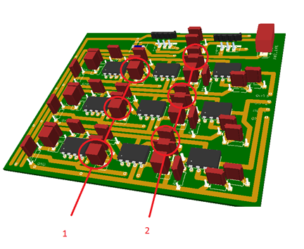
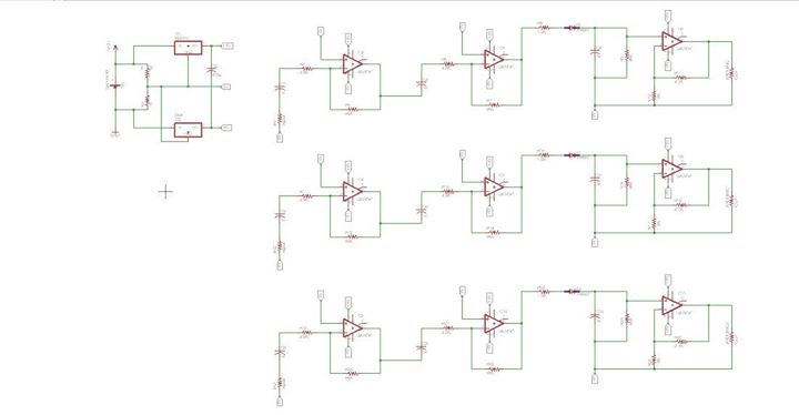
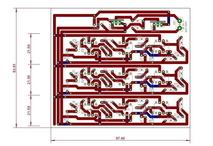
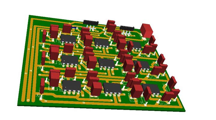
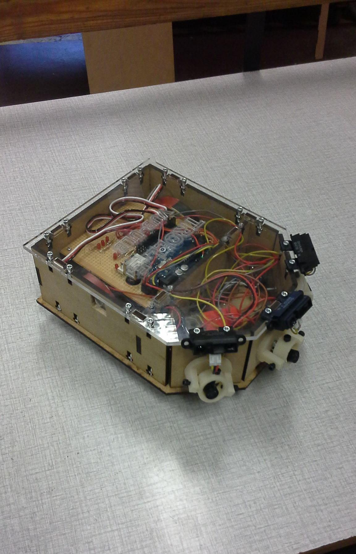
- Finally a micro controller will be the central link between sensors and actuators by making the best decision with the data of the sensors ( who are electronically pre-amplified).
Specifications
Hands-free
Liberate the shopper's hands so that (s)he shops more. No disturbance in any way so the customer can let his automated trolley behind
Follow the shopper
Seamless interaction when the shopper moves. Finding the position of the target customer and move towards him
Stay safe
Avoid knocking the shopper by keeping a minimum distance. Avoiding collision and going around obstacles when possible
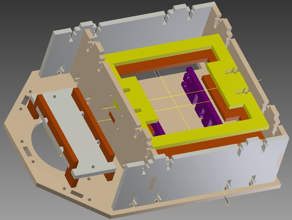
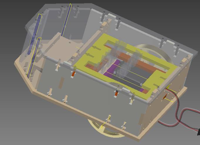
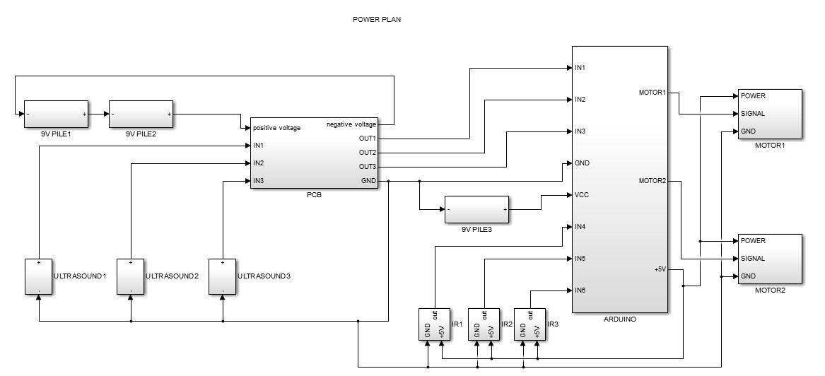
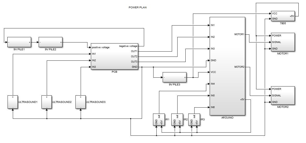
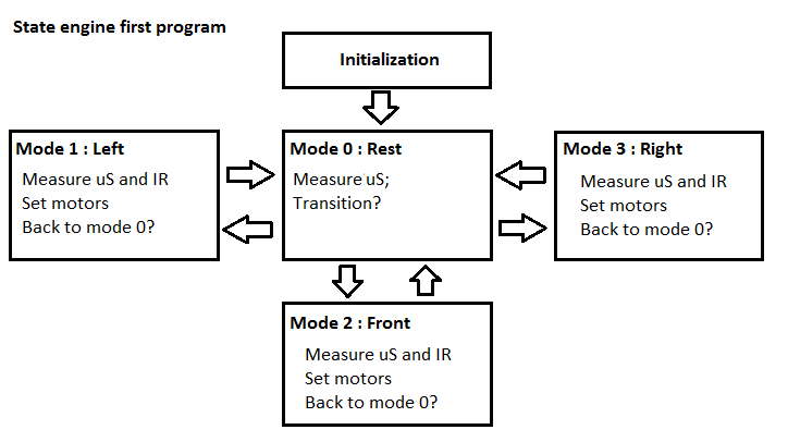
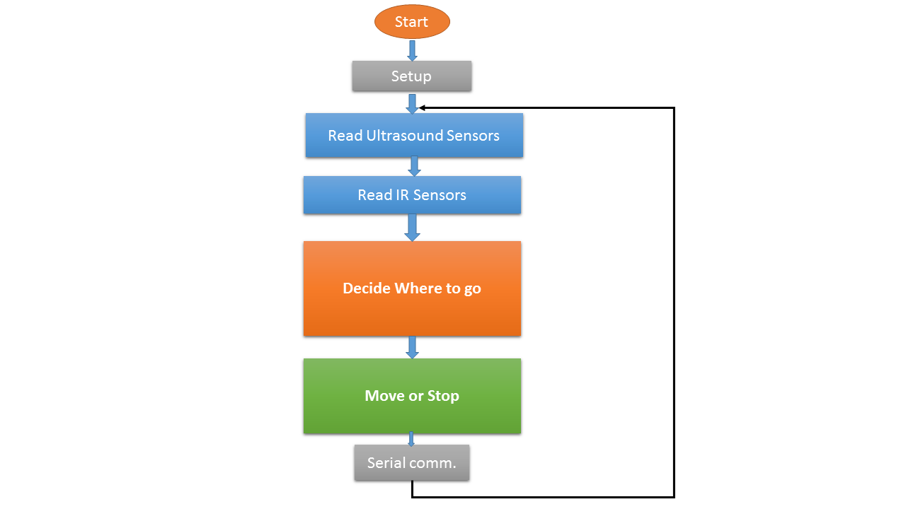
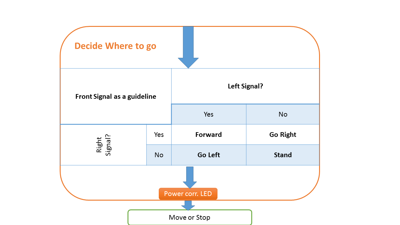
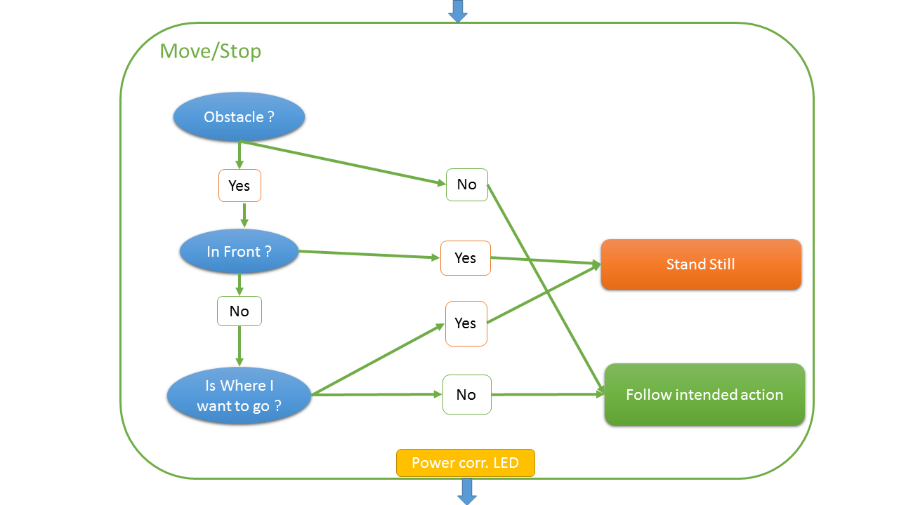
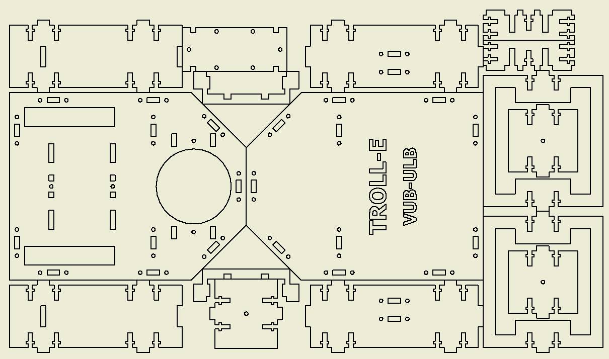
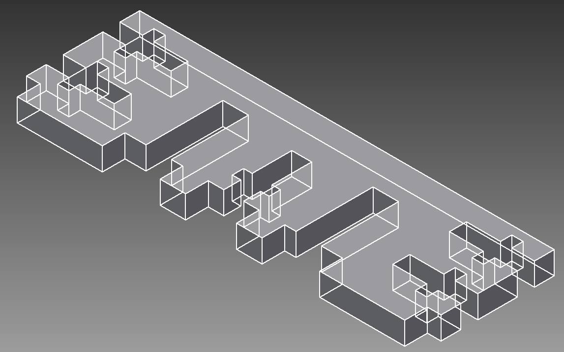
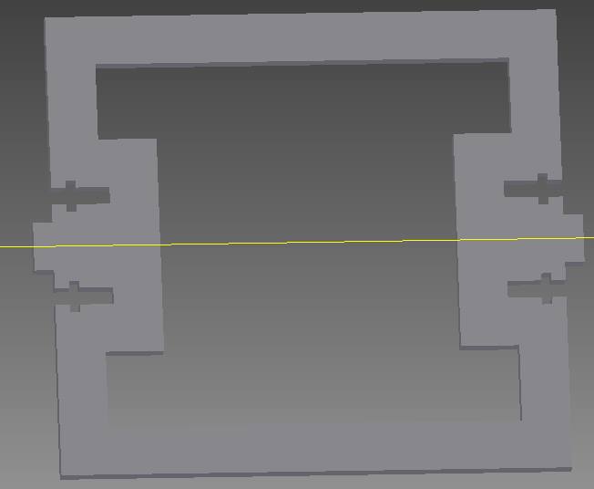
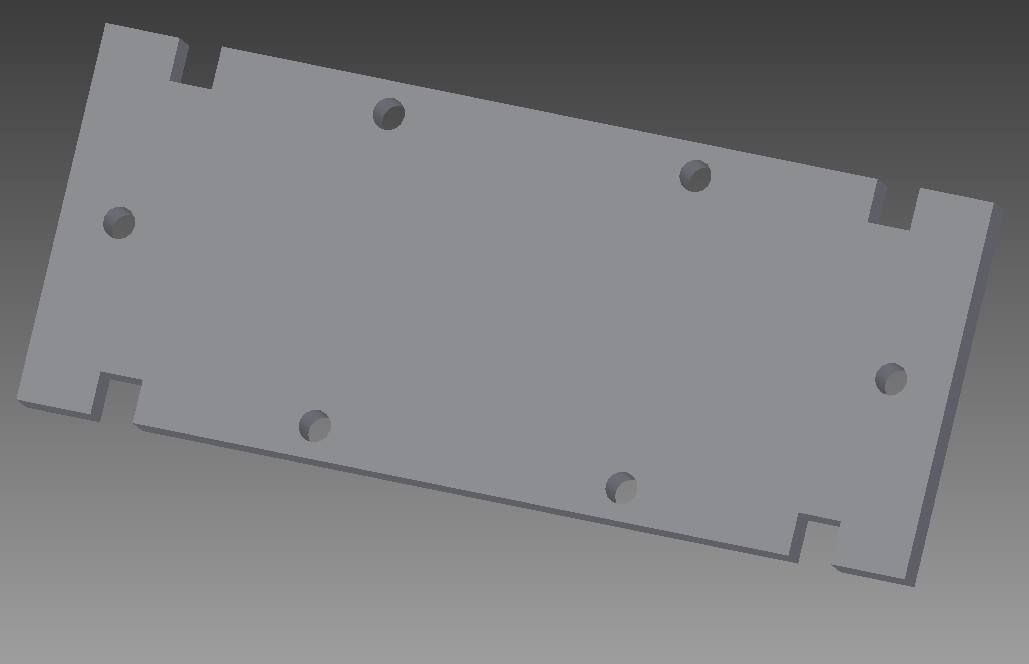
General principle of the robot
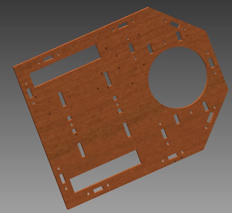
Features of the robot
Results
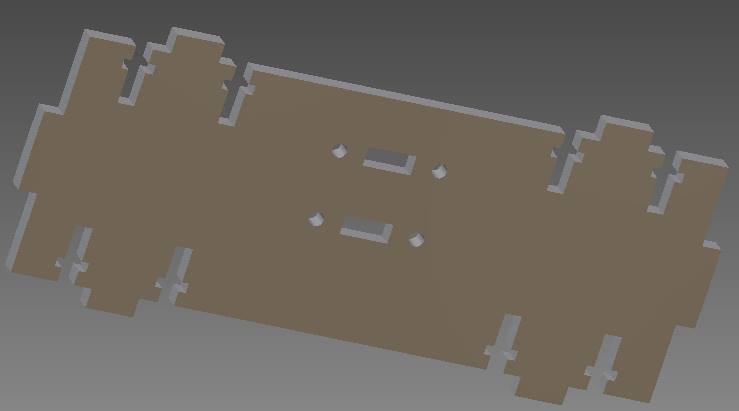
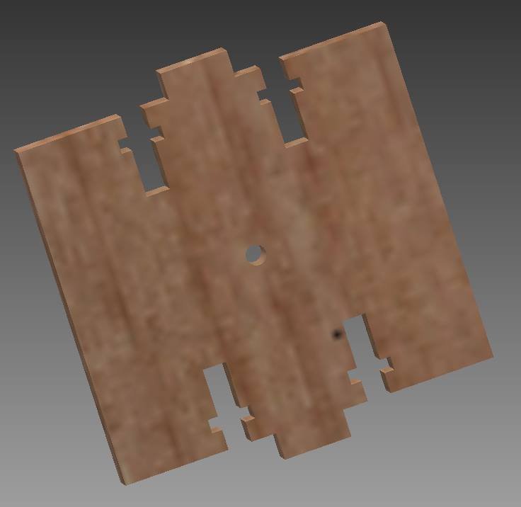
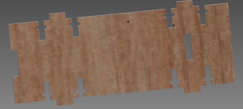
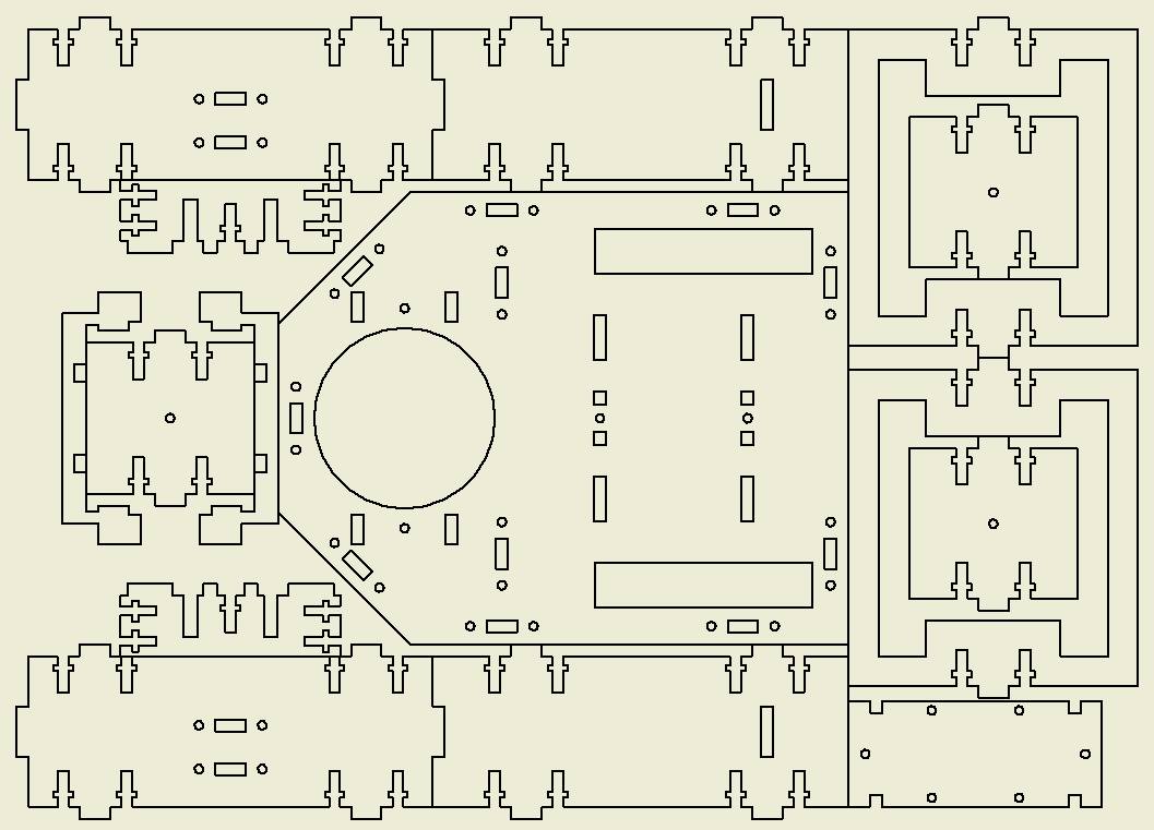
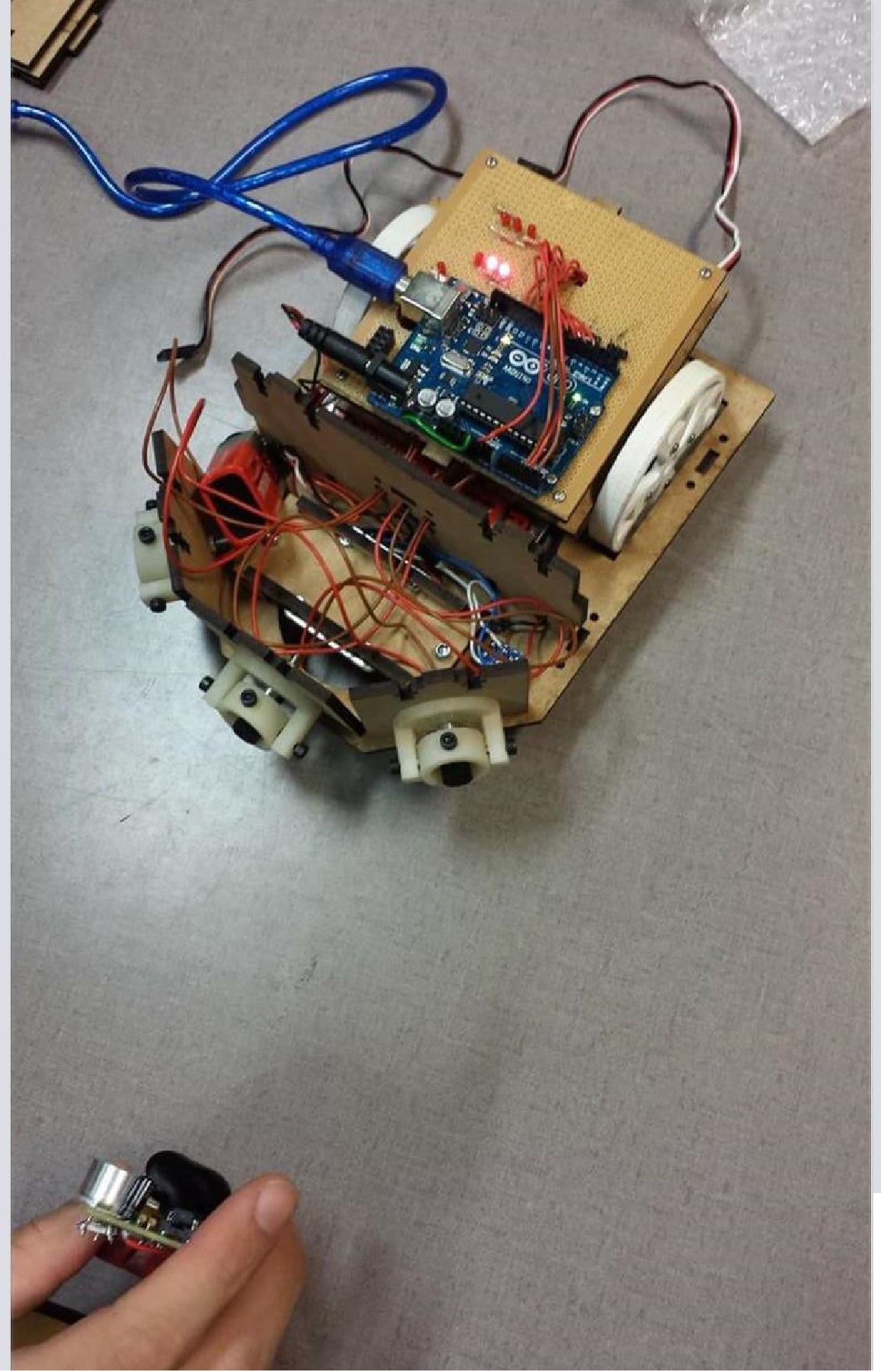
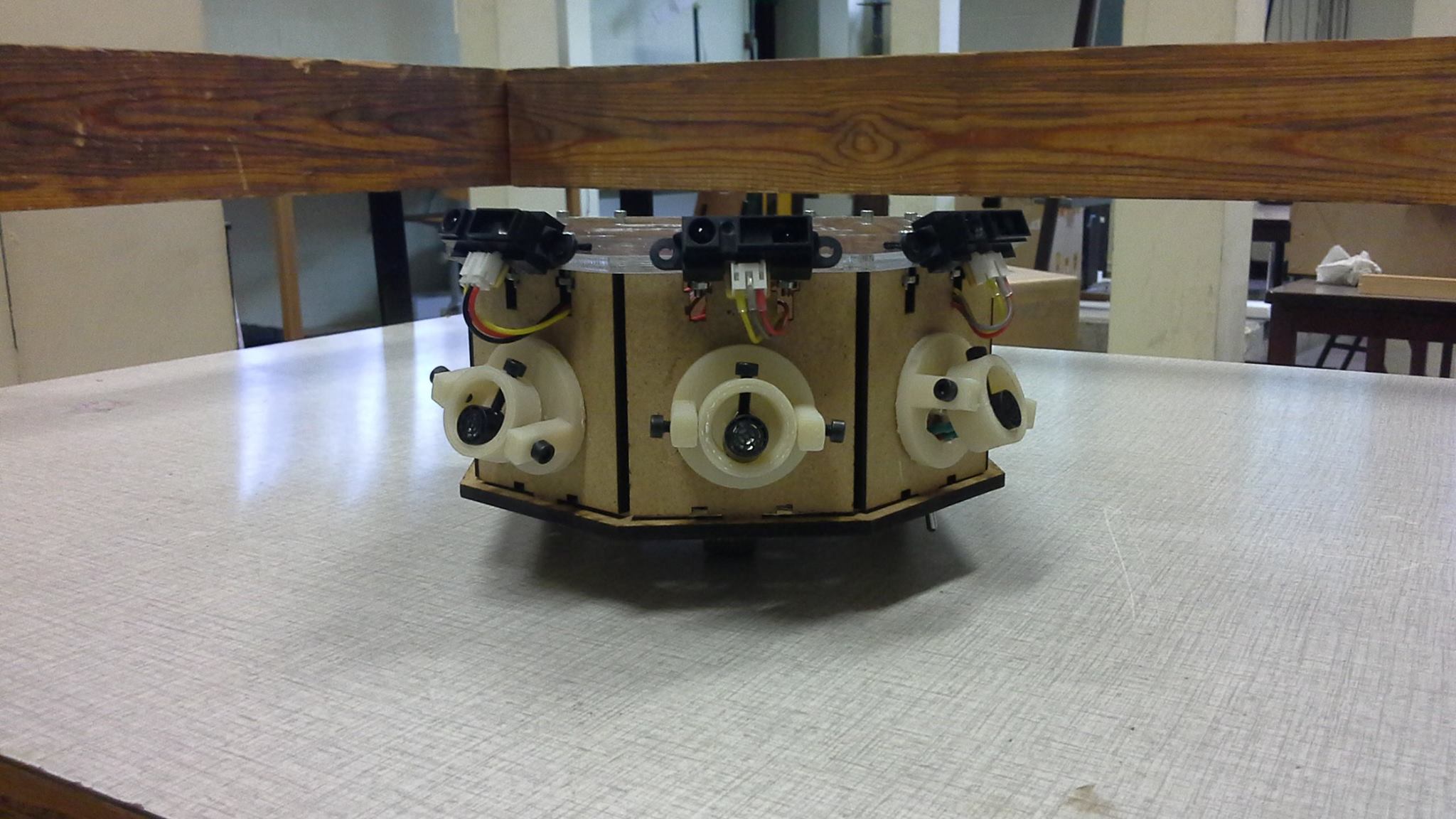
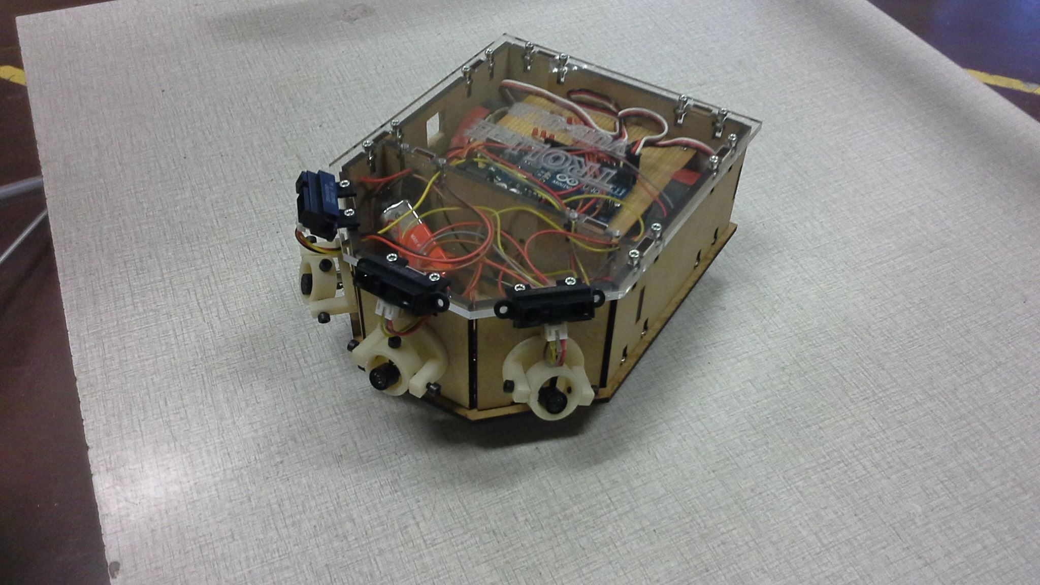
Pictures and Youtube Videos
Pictures